Insulating system with field control elements and method for making same

A technology of isolation structure and field control, which is applied in the direction of electrical components, voltage/current isolation, parts of instruments, etc.

Inactive Publication Date: 2005-07-20
DUROMER KUNSTVERARBEITUNGS
View PDF0 Cites 0 Cited by
  • Summary
  • Abstract
  • Description
  • Claims
  • Application Information

AI Technical Summary

Problems solved by technology

The disadvantage is that this method can only slight

Method used


Image

  • Insulating system with field control elements and method for making same
  • Insulating system with field control elements and method for making same

Examples


Embodiment Construction

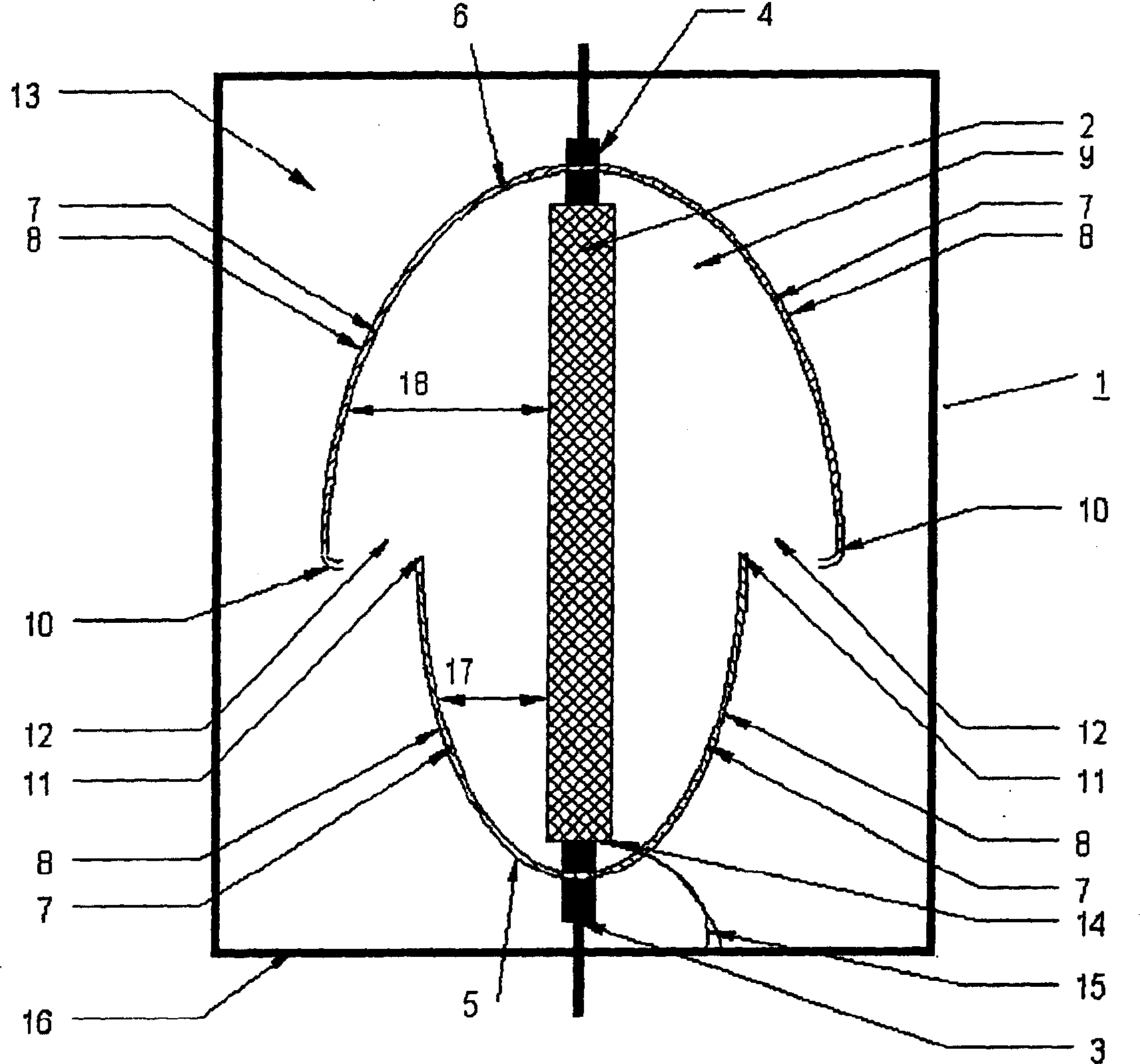
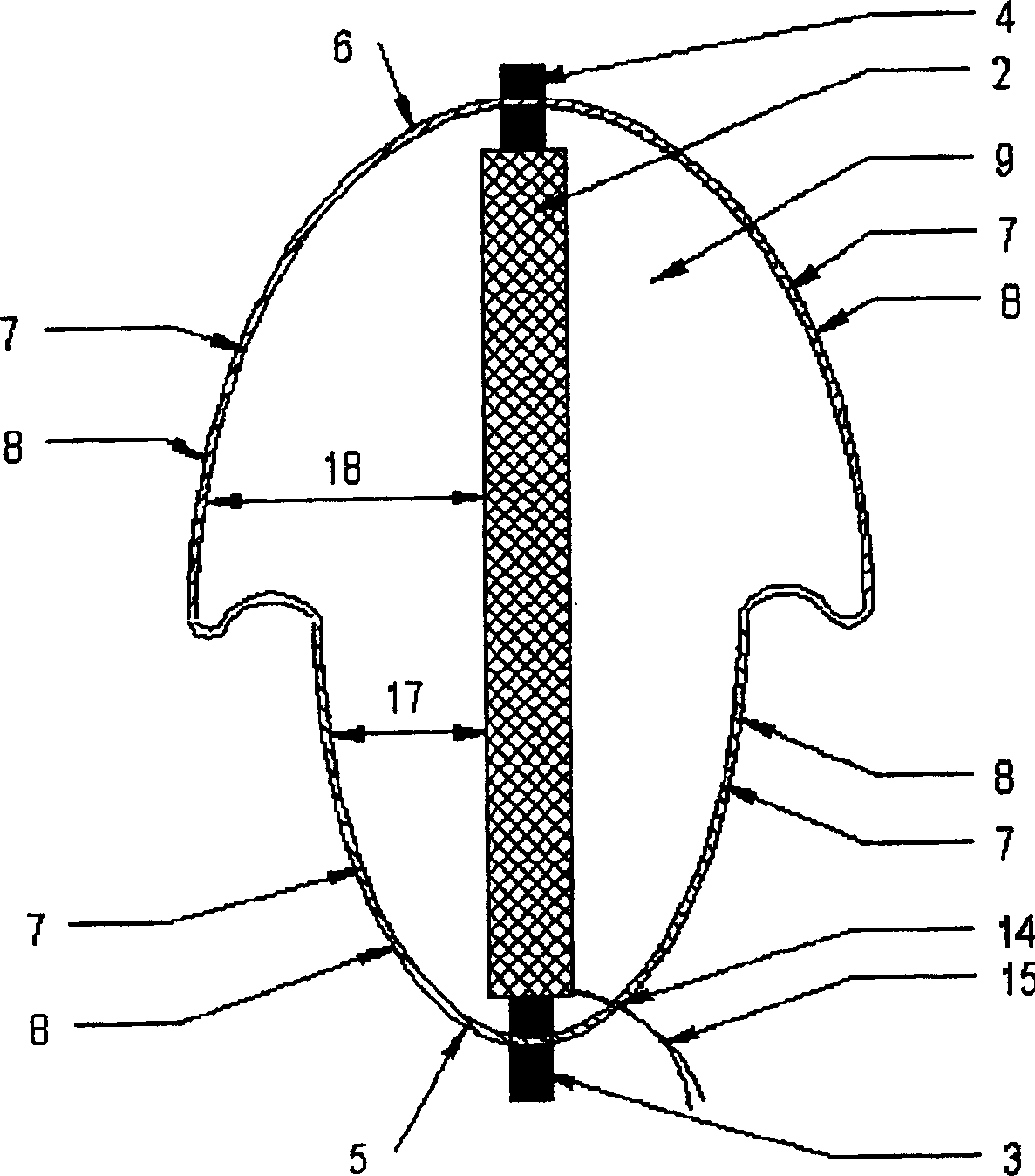
[0025] figure 1 An isolating structure 1 is shown with an ohmic voltage divider 2 which is contacted via a ground connection 3 and a high-voltage connection 4 . Ohmic divider 2 is potted in an inner potting body 9 . A ground-side field control element 5 is arranged around the ground connection end 3 , and a high-voltage side field control element 6 is arranged around the high-voltage connection end 4 . The field control element 5 on the ground side and the field control element 6 on the high voltage side are respectively composed of an inner conductive layer 7 facing the ohmic voltage divider 2 and an outer homogenizing layer 8 facing away from the ohmic voltage divider 2 . The inner potting body 9 has an uncoated region 12 between the outer edge 10 of the field control element 6 on the high-voltage side and the outer edge 11 of the field control element 5 on the ground side. An outer potting body 13 is arranged around the inner potting body 9 , which is covered with the co...


PUM


Abstract

An electrical functional unit (EFU) (2) has a high-voltage connection (4) and an earth connection (3). Field control elements (FCE) (5,6) fit around the EFU and influence the electrical field around the EFU, which is cast in insulating material (9,13) along with the FCE. All these produce an electrical field that is as homogenous as possible and that can be produced with particular benefit. - An INDEPENDENT CLAIM is also included for a method for producing an insulating system for medium high voltage installations.

Description

technical field [0001] The invention relates to an isolating structure, in particular for medium-voltage installations, comprising at least one electrical functional unit with a high-voltage connection and a ground connection, and one or more electrical components arranged around the functional unit for influencing the surroundings of the functional unit. The field control element of the electric field is composed, and the functional unit and the field control element or elements are impregnated in the insulating material. Background technique [0002] Such isolating structures are known in particular in medium-voltage installations, where, for example, the electric field around the measuring transformer is affected and where at the same time a high degree of electrical isolation is required. A pair of metal shields are mostly used here to influence the electric field. In order to form this insulating structure, the measuring transformer is here firstly potted in potting re...

Claims


Application Information

Patent Timeline
IPC IPC(8): G01R15/14G12B17/02H01B9/06H01B17/64H02G5/06H05K9/00
CPCG01R15/04
Inventor 艾莱克尔・乔吉卓臣・厄密斯高特佛莱德・舒斯特
Owner DUROMER KUNSTVERARBEITUNGS
Why Eureka
Try Eureka