Mechanical digger full power control system and method

A full-power control and excavator technology, which is applied to earth movers/shovels, construction, etc., can solve problems such as poor control accuracy, and achieve the effects of improving work efficiency, eliminating impact, and enhancing work efficiency

Inactive Publication Date: 2005-08-10
GUANGXI LIUGONG MASCH CO LTD
View PDF0 Cites 18 Cited by
  • Summary
  • Abstract
  • Description
  • Claims
  • Application Information

AI Technical Summary

Problems solved by technology

[0005] from Figure 4 It can be found that although the PID closed-lo

Method used


Image

  • Mechanical digger full power control system and method
  • Mechanical digger full power control system and method
  • Mechanical digger full power control system and method

Examples


Embodiment Construction

[0027] Among the present invention, include for control system:

[0028] (1) It has a main pump pressure sensor to detect the pressure of the main pump;

[0029] (2) It has a negative flow pressure sensor of the main pump to detect the negative flow pressure of the main pump;

[0030] (3) It has the function of feedforward-feedback adjustment, which is used to receive the data sent by the main pump pressure sensor and the main pump negative flow sensor, perform feedforward-feedback control operation, and superimpose the output signal after operation with the PID adjustment signal Rear drive electro-hydraulic proportional valve.

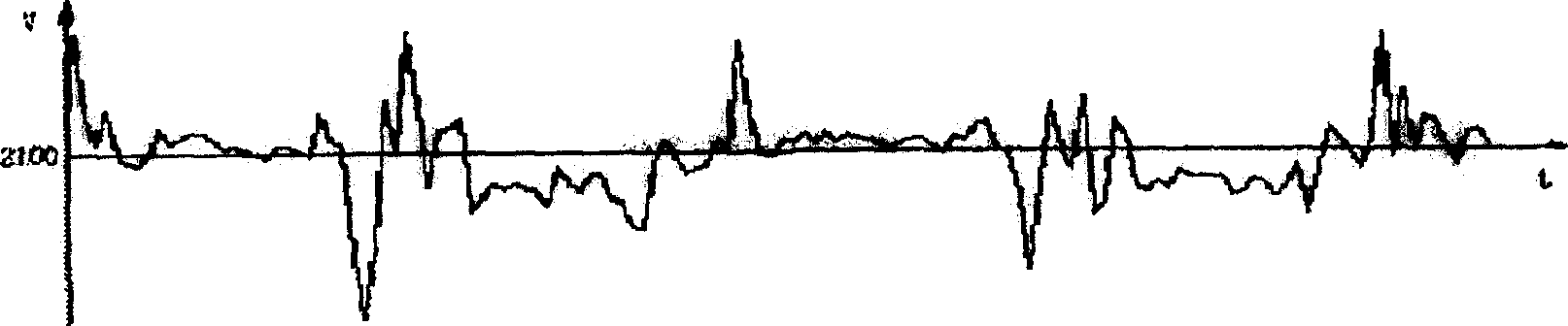
[0031] For the above system, the negative flow pressure changes earlier than the diesel engine speed change when the load changes. Such as Figure 7 shown. It can be seen that before the speed of the diesel engine drops to a given value, the negative flow pressure has already started to drop, and there is a time difference ΔT. The time difference...


PUM


Abstract

The present invention relates to an excavator all-power control system and its method. Said system mainly includes the following components: main pump, feedforward-feedback regulator, PID regulator and electro-hydraulic proportional valve. Said invention also provides the concrete steps of its control method. Said system not only can save energy, but also can raise power utilization rate, and can implement completely matching of absorption power of oil pump and output power of diesel engine.

Description

technical field [0001] The invention relates to an excavator full power control system and method. Background technique [0002] When the original excavator was designed, the power matching method was adopted so that the maximum power absorbed by the oil pump was slightly smaller than the maximum power of the diesel engine corresponding to the throttle position. In other words, as long as the driving torque of the oil pump is slightly smaller than the net output torque of the diesel engine corresponding to the throttle position, the most basic condition for stable operation of the system can be met, as shown in the appendix figure 1 shown. Since the characteristic curve of the constant power pump is an approximate constant power hyperbola composed of two straight lines with different slopes, such as figure 2 Shown: When the load pressure exceeds the starting pressure of the main pump, it will automatically adjust along the characteristic curve dcb. The load changes durin...

Claims


Application Information

Patent Timeline
IPC IPC(8): E02F9/22
Inventor 蔡登胜孙金泉张二平初长祥罗维彭兵
Owner GUANGXI LIUGONG MASCH CO LTD
Why Eureka
Try Eureka