Water energy machine

The technology of a water energy machine and a water turbine is applied to a power machine. It can solve the problems of too dense power station construction, difficult relocation and movement, and high technology, and achieve the effects of saving land resources, increasing flow, and reducing water resistance

Inactive Publication Date: 2005-08-10
杨建宝
View PDF0 Cites 9 Cited by
  • Summary
  • Abstract
  • Description
  • Claims
  • Application Information

AI Technical Summary

Problems solved by technology

[0004] The construction of a hydropower station is not only restricted by geographical conditions, but also requires a place with a large drop and abundant water sources where a large amount of water can be built and stored. The purpose is to increase the potential energy, kinetic energy and pressure energy, and maintain stable and long-term power generation. The project requires high technology, takes a long time, and covers a large area. It has a certain impact on the lives of local people and the environment and ecology. Some power stations have run dry or are too densely built, which affects power generation and water conservancy, and it is difficult to relocate and move.

Method used


Image

  • Water energy machine
  • Water energy machine

Examples


Embodiment 1

[0036] Embodiment 1 Water mobile power supply

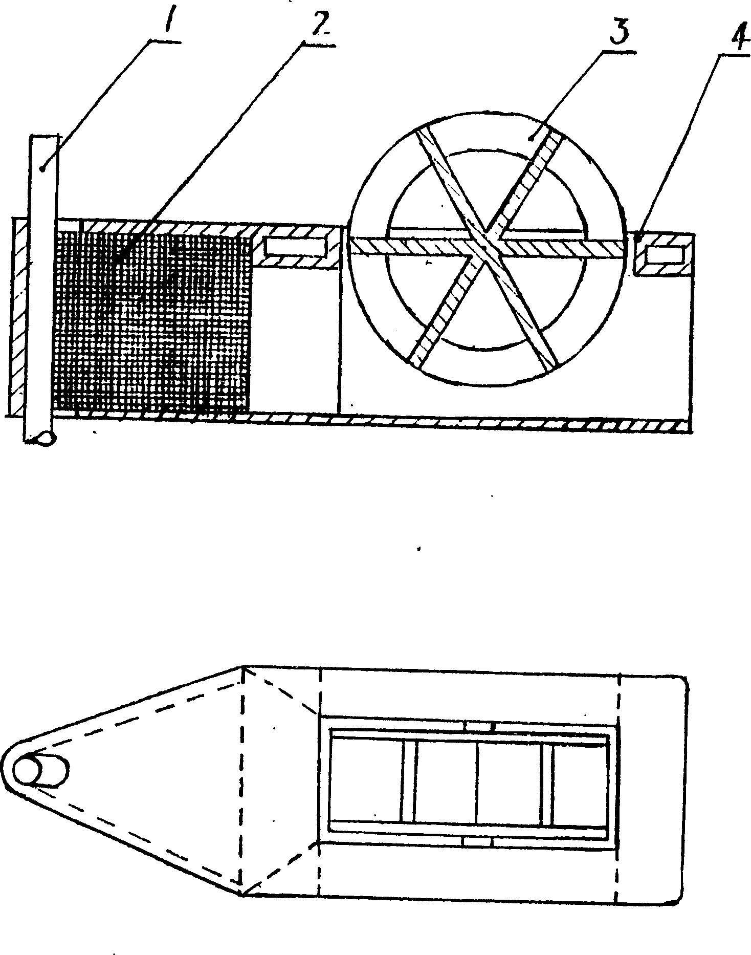
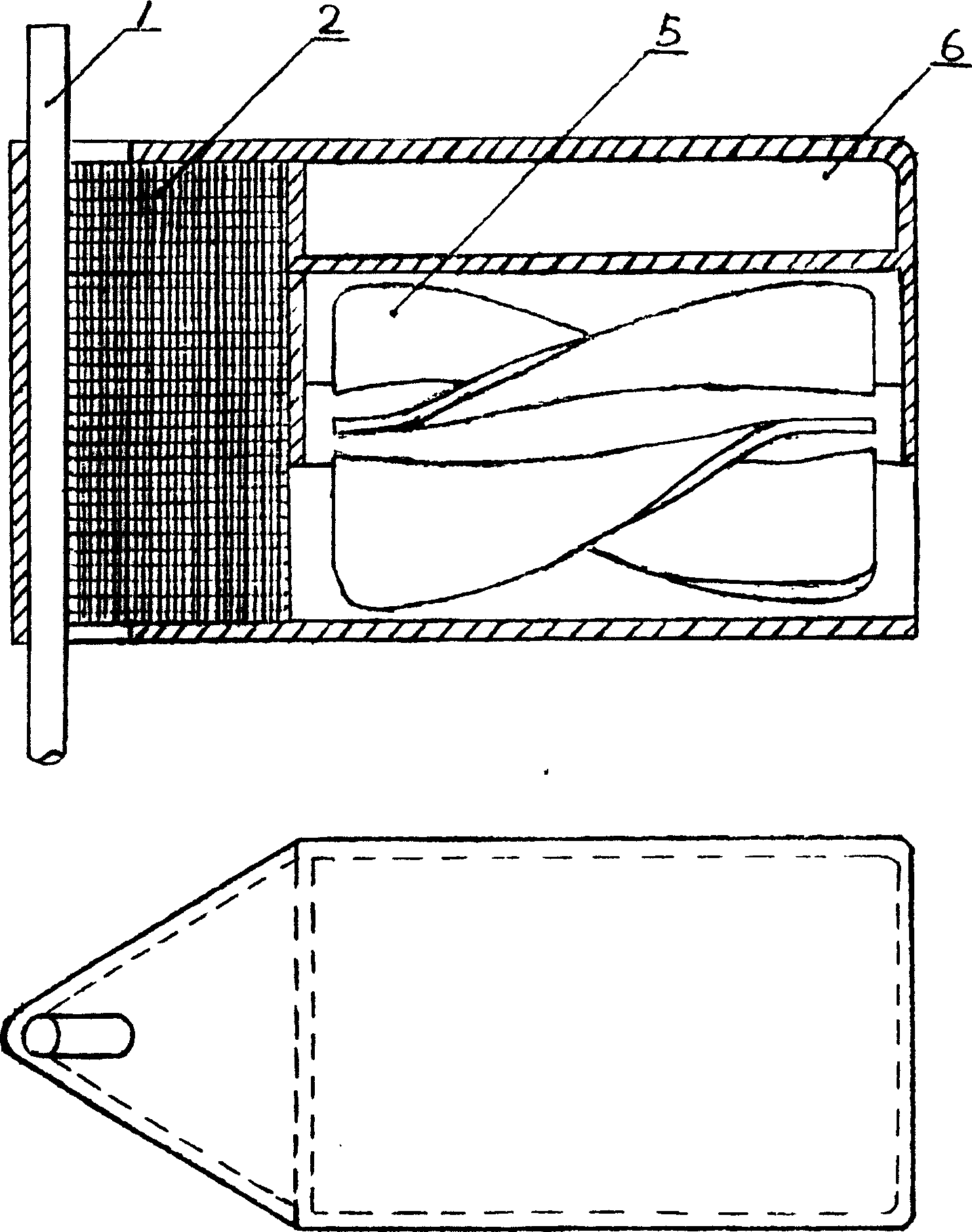
[0037] A small generator is equipped on the small water energy machine, the ropes and cables are combined, fixed on the front end of the water energy machine and waterproof measures such as sealing are taken. When in use, put it into the water flow and bind the cable at the other end to supply power. It is very convenient to move and has a wide range of applications.

Embodiment 2

[0038] Example 2 Automatic bleaching machine

[0039] The present invention is equipped with a reducer mechanical mechanism or a hydraulic system on the water energy machine, just like the principle of a dump truck, to drive the trough-shaped net installed on the water surface in front of the water energy machine, and periodically unload the floating objects caught on the shore in the cage. In order to avoid missed fishing, double-groove nets can be arranged in front and back, and take turns to fish and unload together. It is a water cleaning and environmental protection machine that protects the safety of the waterway of the power station and aquaculture, and reduces water pollution. The trough net is replaced with a fishing net in the water to become a periodic automatic fishing machine.

Embodiment 3

[0040] Embodiment 3 Self-propelled automatic sand scratching machine

[0041] In the report on water and sediment regulation of the Yellow River, high-pressure water heads are used to impact the river bed to stir up the sediment, so that the water can carry the sediment away to improve the river bed. In the present invention, the steel wire rope is driven by a water energy machine to rotate the tail of the river bed to form a wire brush to stir the silt and let the water flow take it away. The main shaft is equipped with an overload release, which can usually be bypassed when it encounters reef rocks, etc. It also has a protective effect in case of being stuck. The machine is not damaged.

[0042] On this basis, the technical scheme of self-propelled is: establish deceleration clutch, reel, left and right wire rope and bump. The two steel wire ropes are fixed on the reel at the front end of the machine table parallel to each other. Its working principle is: while the water ...


PUM


Abstract

The present invention relates to a water engine machine capable of extensively and fully utilizing natural water flow energy source. Its technical scheme is characterized by that a light high-sensitivity hydraulic turbine is mounted on the floating table or seat table, said whole machine can be floated or fixed in the water toward water flow, then the hydraulic turbine can be rotated so as to obtain the low-cost green energy source.

Description

1. Technical field [0001] The invention belongs to a power machine, in particular a power machine which can widely and fully utilize natural water flow energy. 2. Technical Background [0002] Energy is one of today's scientific and technological gatherings. Experts and scholars from all over the world are working hard to explore and solve problems, especially environmentally friendly, durable and cheap green energy. Consult and study the information on energy development and utilization and hydropower in the world today. Hydropower is the cleanest, environmentally friendly, durable and cheap among water, wind, kerosene, nuclear power generation. In the natural flow of water, there is no machine that uses water energy to directly drive work in water. [0003] At present, water energy is used to generate electricity. There are two types, one is special power stations that use wave power generation and tidal power generation on the ocean, and the other is dam-type power statio...

Claims


Application Information

Patent Timeline
Patent Type & Authority Applications(China)
IPC IPC(8): E02B9/08F03B13/22
CPCY02E10/38Y02E10/30
Inventor 杨建宝
Owner 杨建宝
Why Eureka
Try Eureka