Heat pipe and manufacturing method therefor

A manufacturing method and technology for heat pipes, which are applied in indirect heat exchangers, heat exchange equipment, lighting and heating equipment, etc., can solve problems such as affecting the heat dissipation performance of heat pipes and reducing the heat conduction efficiency of heat pipes and heating elements.

Inactive Publication Date: 2005-08-17
HONG FU JIN PRECISION IND (SHENZHEN) CO LTD +1
View PDF0 Cites 10 Cited by
  • Summary
  • Abstract
  • Description
  • Claims
  • Application Information

AI Technical Summary

Problems solved by technology

Such as the above two methods of processing micro heat pipes, it is very easy to form protrusions on the two parts of the flat heat pipes in the process of manufacturing micro heat pipes, thereby reducing the heat conduction efficiency between the heat pipes and heating elements; When the vapor pressure inside is high, the two parts of the heat pipe will separate from each other due to expansion, which will affect the heat dissipation performance of the heat pipe

Method used


Image

  • Heat pipe and manufacturing method therefor
  • Heat pipe and manufacturing method therefor
  • Heat pipe and manufacturing method therefor

Examples


Embodiment Construction

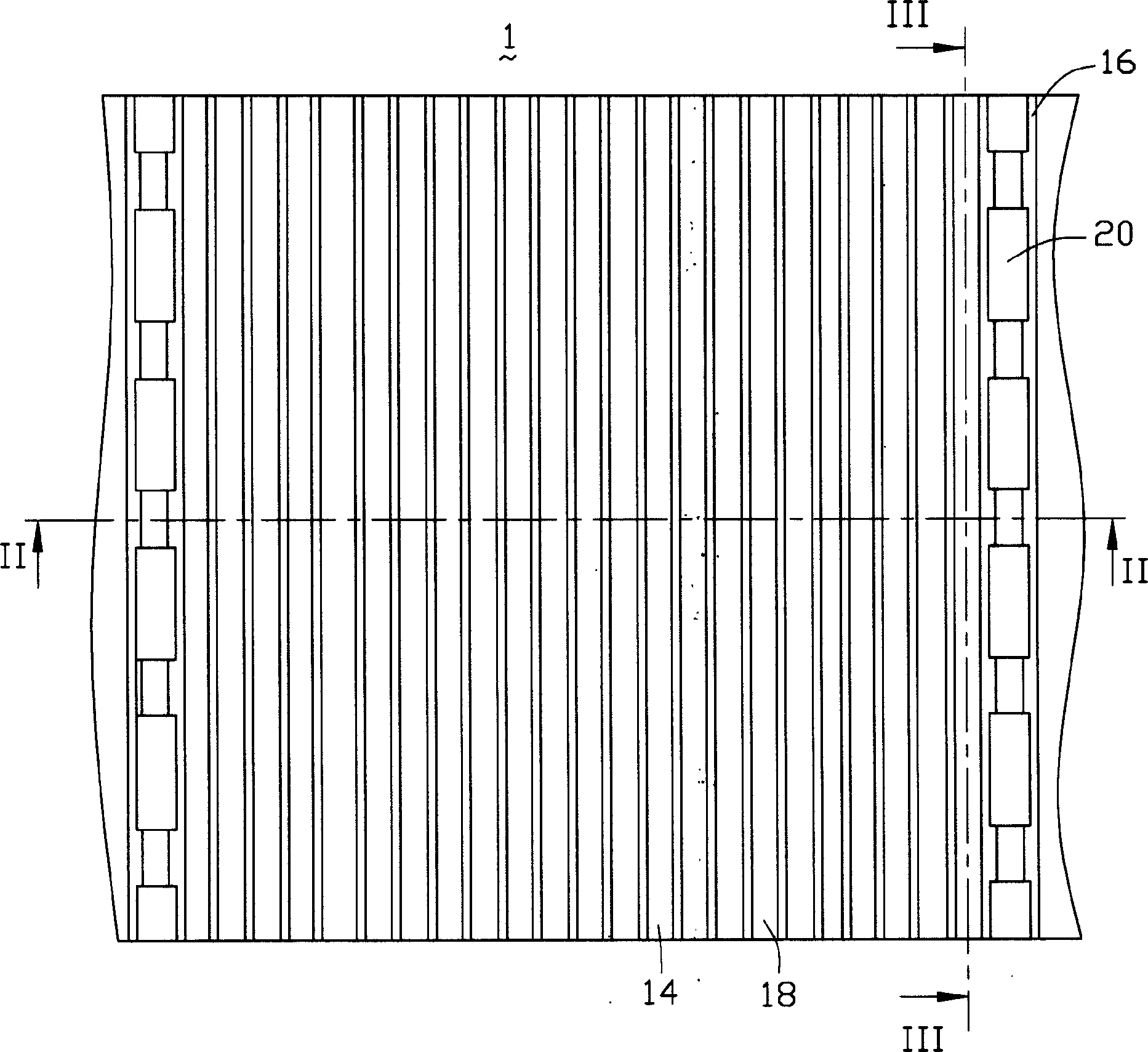
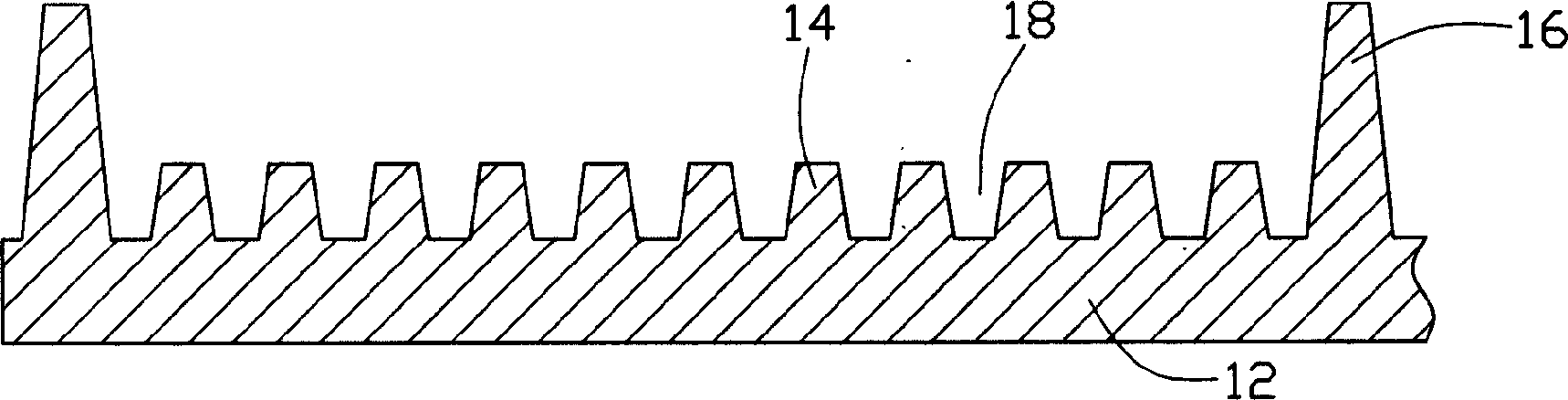
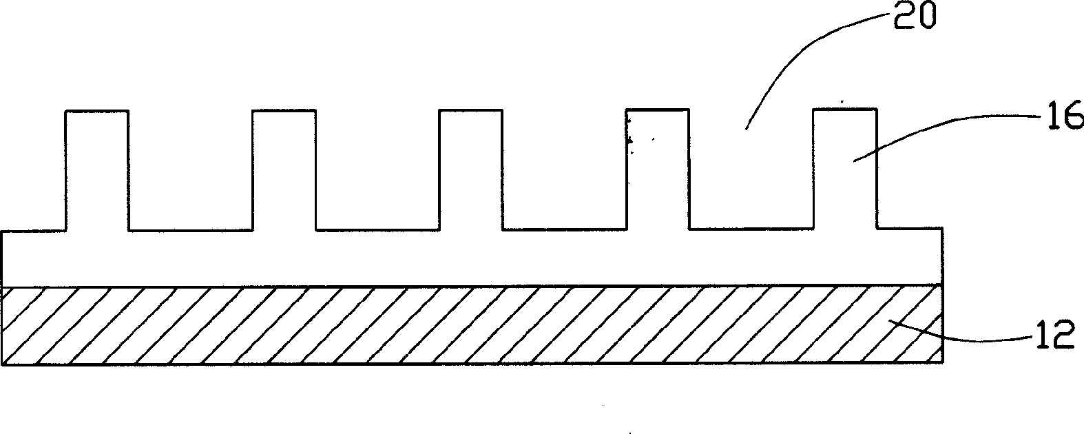
[0017] Please refer to Figure 1 to Figure 3 The present invention is shown as a flat panel 1 with micro-grooves. The flat panel 1 includes a base body 12 and a number of short fins 14 and long fins 16 arranged on the base body 12, and forms between adjacent short and long fins 14 and 16. Several micro-grooves 18. These short fins 14 and long fins 16 are alternately arranged on the base 12 , a number of short fins 14 are provided between two adjacent long fins 16 , and a number of gaps 20 are provided in each long fin 16 . The plate 1 can be made of copper, bronze, aluminum, stainless steel, nickel and alloys thereof. The cross-sectional shape of the groove 18 is preferably trapezoidal, with a width of about 0.1-0.5 mm and a height of about 0.1-0.6 mm, and the width and length of the plate 1 can be selected according to needs. The plate 1 is symmetrically divided into two parts, called the first part and the second part respectively.

[0018] Figure 4 and Figure 5 Shown...


PUM


Abstract

Disclosed is a heat pipe which comprises a first substrate including at least a first short fim slice and at least a first long fim slice and a second substrate including at least a second short fim slice and at least a second long fim slice, wherein, plough grooves between adjacent short and long fim slices form flowage channels for operating fluids, the first and the second long fim slices are respectively connected with corresponding plough grooves on the second substrate and the first substrate, and the long fim slices are connected with the corresponding plough grooves through welding manner.The method for fabricating the heat pipe comprises 1) providing a flat plate which includes a substrate and a short and a long fim slices arranged on the substrate, with plough grooves formed between the short and the long fim slices; 2) buckling a first part of the flat plate towards a second part of the flat plate to contact the long fim slices on the first part and the second part respectively with the corresponding plough grooves on the second part and the first part; 3) connecting the long fim slice with the corresponding plough groove through welding manner; and 4) sealing the two terminal parts of the flat plate.

Description

【Technical field】 [0001] The invention relates to a heat pipe and a manufacturing method thereof, in particular to a micro-grooved heat pipe and a manufacturing method thereof. 【Background technique】 [0002] In the industrial production process, various parts and components will generate heat during operation. For example, in the electronic information industry, computer components will generate a lot of heat during work. Various electronic components, integrated circuits, especially the central processing unit, will generate a lot of heat during the working process. If the heat generated is not removed in time, the heat will accumulate and cause the temperature to rise, which will seriously affect the operation of electronic components. For example, a Pentium processor including millions of transistors, if the heat generated during its operation cannot be removed in time, these transistors are more likely to damage the processor due to overheating, and even damage other co...

Claims


Application Information

Patent Timeline
Patent Type & Authority Applications(China)
IPC IPC(8): F28D15/02F28D15/04
CPCF28D15/0233F28D15/046F28F2260/02Y10T29/49353
Inventor 王亚雄黄中元
Owner HONG FU JIN PRECISION IND (SHENZHEN) CO LTD
Why Eureka
Try Eureka