Method of vibration and extrusion for cast-in-place concrete in pile hole and its vibration rod device

A concrete and vibrating rod technology, applied in sheet pile wall, building material processing, building structure, etc., can solve the problems of strong vibration, unsuitability, high noise, etc., and achieve low power, low energy loss, and environmental impact. small effect

Inactive Publication Date: 2005-08-24
北京市机械施工集团有限公司
View PDF0 Cites 13 Cited by
  • Summary
  • Abstract
  • Description
  • Claims
  • Application Information

AI Technical Summary

Problems solved by technology

However, the method of sinking directly into the steel pipe by vibration to form a hole to complete the CFG pile has large noise, strong vibration, and pollutes the environment, so it is no longer suitable for application in urban construction projects.

Method used


Image

  • Method of vibration and extrusion for cast-in-place concrete in pile hole and its vibration rod device
  • Method of vibration and extrusion for cast-in-place concrete in pile hole and its vibration rod device
  • Method of vibration and extrusion for cast-in-place concrete in pile hole and its vibration rod device

Examples


Embodiment 1

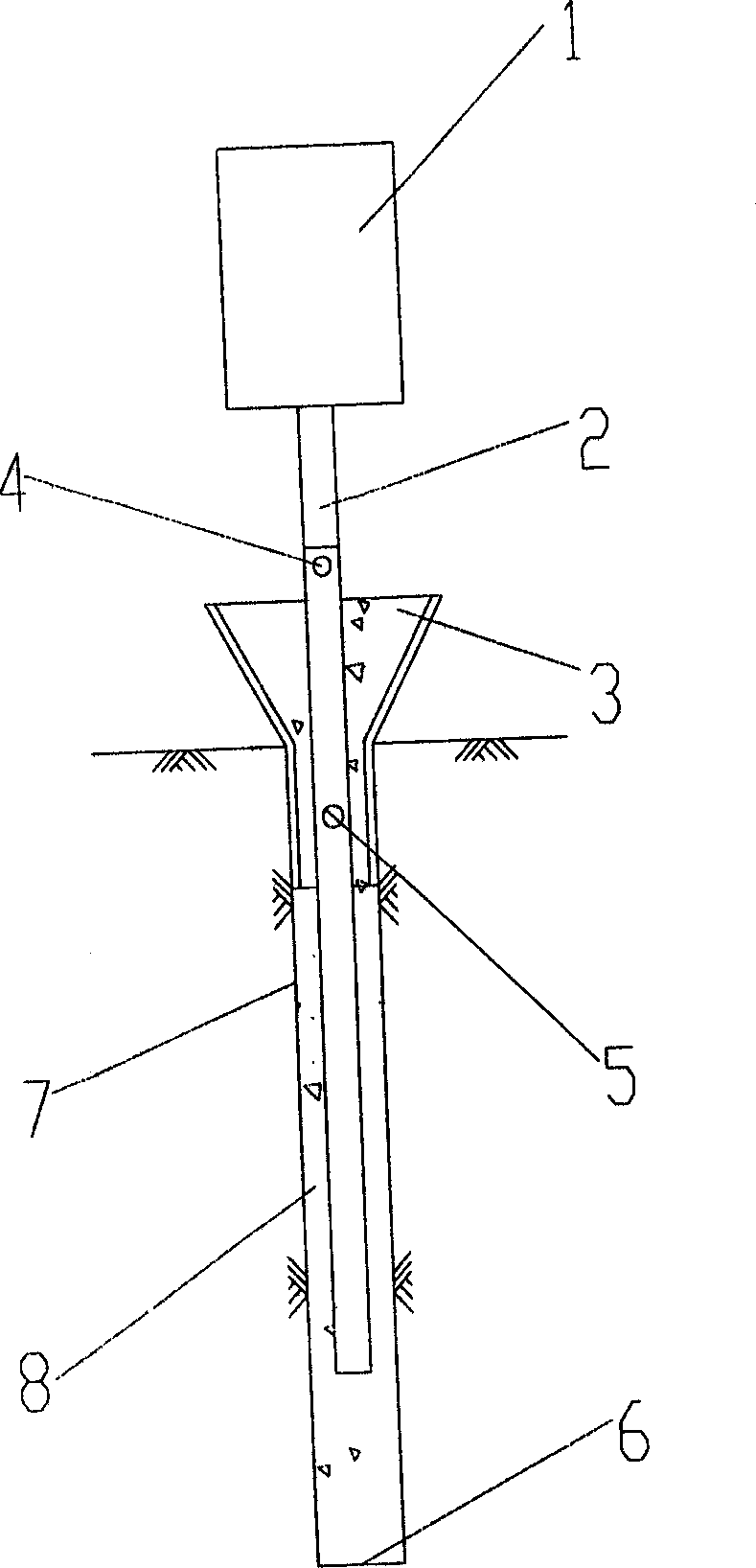
[0019] Embodiment 1: refer to figure 1 Schematic diagram of the construction of a single steel pipe force transmission member vibrator rod. It describes the method of vibrating and compacting the concrete in the pile hole of plain concrete piles when the pile diameter is small. The vibration source 1 is connected with the steel pipe 2 to form a vibration rod.

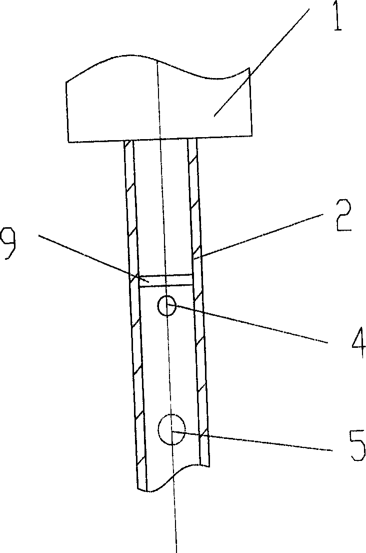
[0020] refer to figure 2 , the upper part of the steel pipe 2 has a vent hole 4, and the upper edge of the vent hole 4 in the inner cavity of the steel pipe is welded with a sealing partition 9. The middle and upper part of the steel pipe 2 opens a material hole 5 . The diameter of the feed hole 5 is larger than that of the air hole 4 . The lower end of the steel pipe 2 is open.

[0021] Its technological process is:

[0022] 1. Drilling

[0023] 2. Pour concrete into the pile hole.

[0024] 3. Clean up the dregs at the orifice, and insert the orifice protection barrel 3 into the pile hole. Into the concrete s...

Embodiment 2

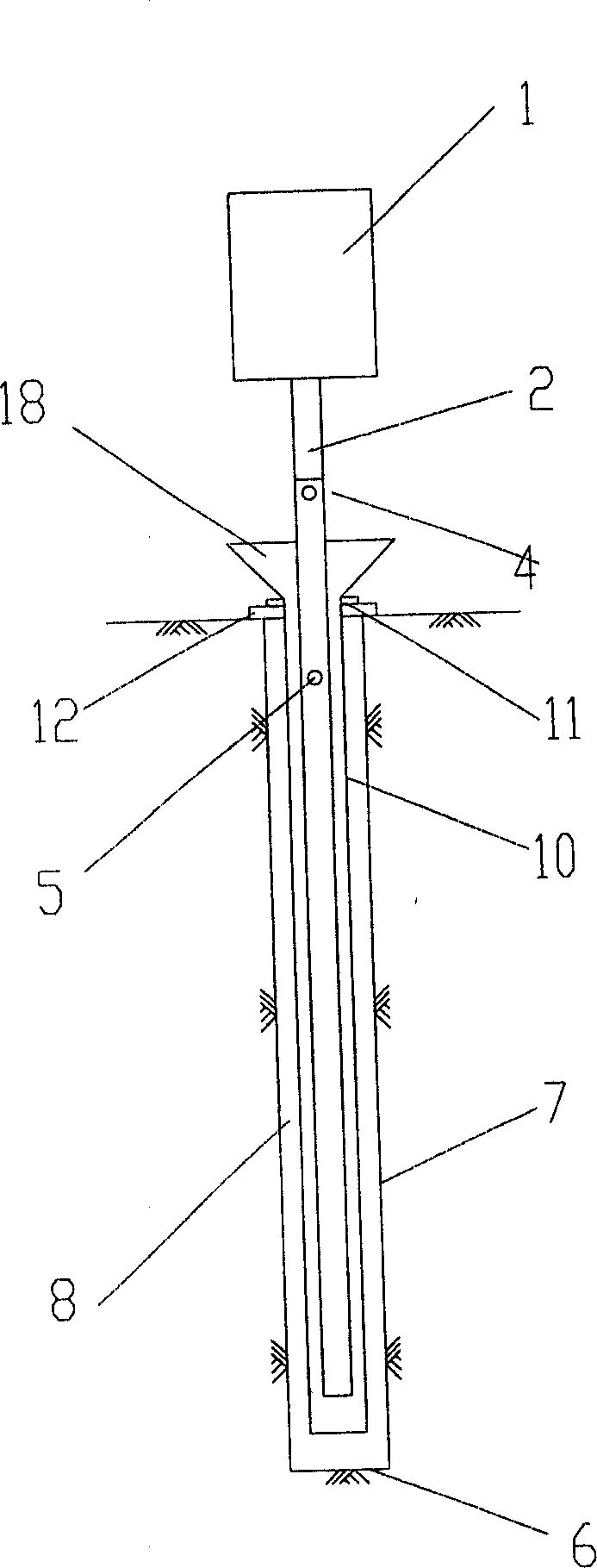
[0030] Example 2: image 3 It is a schematic diagram of the construction of the vibrating rod of the set of double steel pipe force transmission components. This method is adopted when the pile diameter is large, the pile length is long, and there is mud stagnant in the upper part of the cast-in-place concrete in the pile hole. Upper mud. Internal steel pipe 2 with figure 1 The structure shown is the same, with the lower end open. The outer steel pipe 10 is open at the lower end and the upper end, the pipe wall is not perforated, and the lower end is provided with a temporary seal. Its construction process is:

[0031] 1. Drill holes in place.

[0032] 2. Put the reinforcement cage and detect the sediment at the bottom of the hole.

[0033] 3. Lower the conduit and pour concrete underwater. Pull out the concrete pipe.

[0034] 4. Temporarily seal the lower part of the double-tube ultra-long vibrating rod in the set, and after inserting it into the concrete, remove the ...


PUM


Abstract

A method for pouring concrete into pile hole and compressing and its vibrator are disclosed; including the following steps: (1) according to the work mode of concrete pile to choose the type of vibrator, use shape steel or steel pipe as the structural force-passing element; when there is mud staying in the upper part, use steel pipe; (2) pour concrete into the pile hole; (3) insert the vibrator into the concrete to vibrate and stress. The method suits for CFG pile dry work pouring pile method, wet work circulative pouring method and digging-drilling method etc.

Description

technical field [0001] The invention belongs to the technical field of foundation construction and relates to the construction technology of concrete filling piles. Specifically, it is a method and device for vibrating and compacting cast-in-situ concrete in pile holes. Background technique [0002] In the construction of cast-in-place concrete piles, there is a type of reinforced concrete pile, with a reinforcement cage placed on the pile body; there is also a type of plain concrete pile, without a reinforcement cage placed on the pile body. For hole-forming and pile-forming operations, after placing the reinforcement cage and pouring concrete, the concrete several meters below the hole is often vibrated and compacted with a vibrating rod. Due to the limited length of the vibrating rod. Concrete over the full length of the pile cannot be vibrated. [0003] The engineering piles completed by using the method of wet operation mud retaining wall to form piles, after being p...

Claims


Application Information

Patent Timeline
Patent Type & Authority Applications(China)
IPC IPC(8): E02D5/36E04G21/08
Inventor 常乃麟张治华李虹游大江
Owner 北京市机械施工集团有限公司
Why Eureka
Try Eureka