Spiral turbo-hydroturbine

A technology of spiral turbines and water turbines, applied in hydroelectric power generation, mechanical equipment, machines/engines, etc., can solve the problems that affect the improvement of the power and water energy conversion efficiency of water turbines, large water energy, etc., and achieve high water energy utilization and simple structure Effect

Inactive Publication Date: 2005-08-24
徐在林
View PDF0 Cites 5 Cited by
  • Summary
  • Abstract
  • Description
  • Claims
  • Application Information

AI Technical Summary

Problems solved by technology

[0002] No matter the water turbine in the prior art is counterattack type, mixed flow type, impact type or propeller type, the flowing water acts on the blades of the water turbine and leaves in such a short moment, otherwise the water discharge will impact the blades of the water turbine The resistance will affect the power increase of the water turbine. On the other hand, the water still has a certain amount of energy due to the rapid departure, and the faster it leaves, the greater the loss of water energy.
The above are two technical problems that have not been well resolved in the current technology of water turbines, which directly affect the increase of power of water turbines and the improvement of water energy conversion efficiency

Method used


Image

  • Spiral turbo-hydroturbine
  • Spiral turbo-hydroturbine

Examples


Embodiment 1

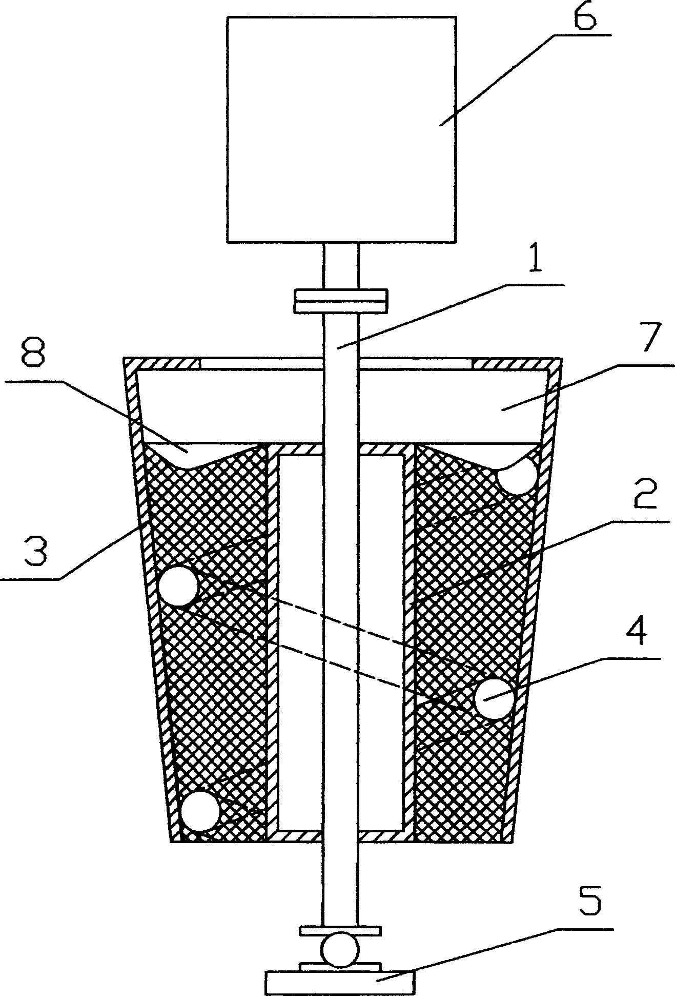
[0012] Embodiment one: if figure 1 As shown, the screw turbine includes a main shaft 1, the main shaft 1 is vertically arranged, and an inner vertical tube 2 and an outer vertical tube 3 are fixedly installed on the main shaft 1, and a helical shaft is arranged between the inner vertical tube 2 and the outer vertical tube 3. The water flow channel 4, the lower end of the main shaft 1 is provided with a support seat 5, the upper end of the main shaft is connected with the generator 6, and the upper end of the outer cylinder 3 is provided with a water collection chamber 7, and the top of the rotor of the spiral water flow channel 4 is provided with multiple shocks Dimple 8, the shape of the outer surface of the impact dimple 8 is similar to the upper surface of the blade turbine, which is beneficial to the conversion of water kinetic energy.

[0013] The outer vertical cylinder 3 fixedly installed on the main shaft 1 is conical, and the spiral water flow channel 4 is a conical s...

Embodiment 2

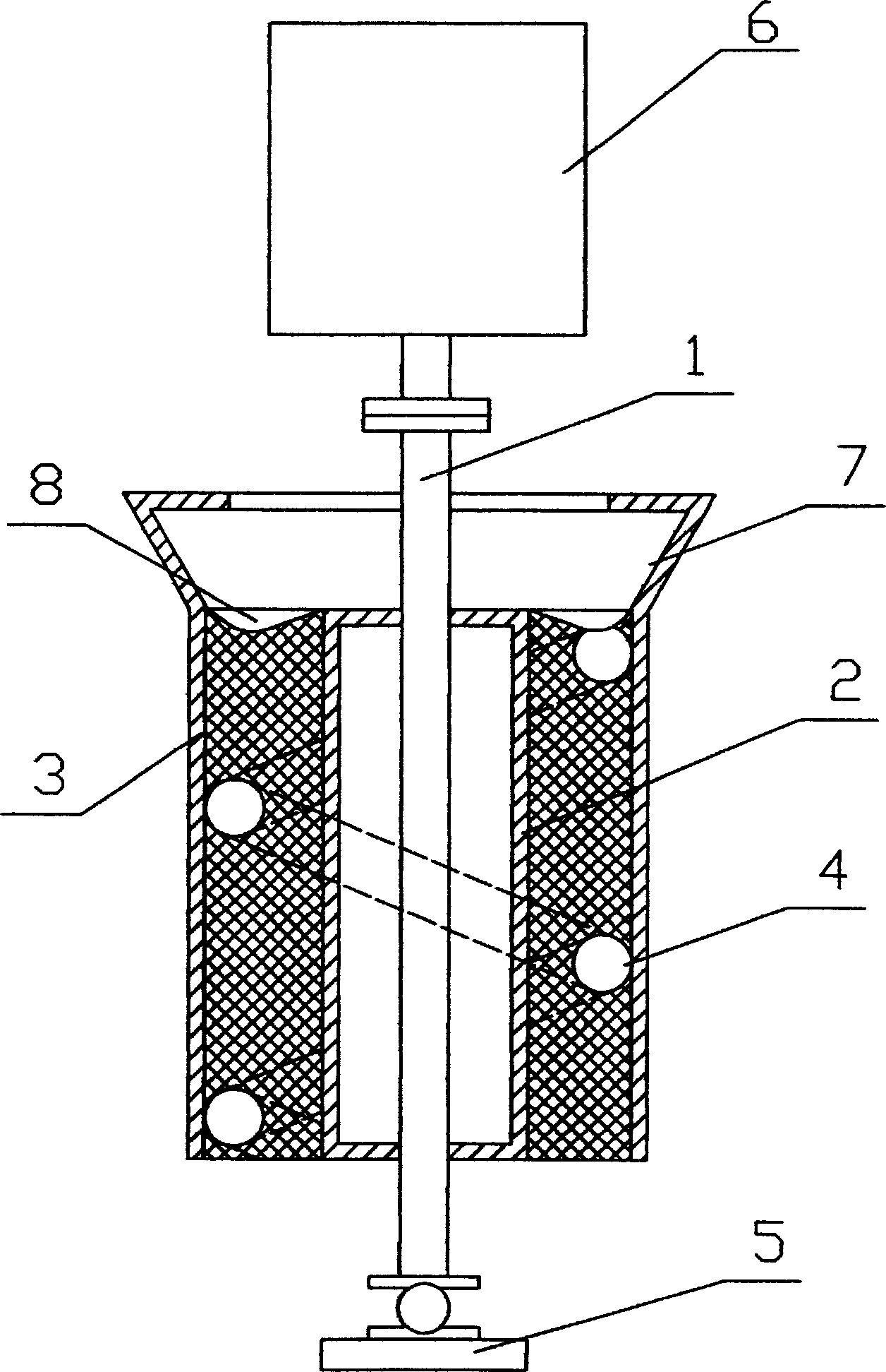
[0014] Embodiment two: if figure 2 As shown, the screw turbine includes a main shaft 1, the main shaft 1 is vertically arranged, and an inner vertical tube 2 and an outer vertical tube 3 are fixedly installed on the main shaft 1, and a helical shaft is arranged between the inner vertical tube 2 and the outer vertical tube 3. The water flow channel 4, the lower end of the main shaft 1 is provided with a support seat 5, the upper end of the main shaft is connected with the generator 6, the upper end of the outer cylinder 3 is provided with a water collection chamber 7, and the top of the rotor of the spiral water flow channel 4 is provided with multiple shocks Dimple 8, the shape of the outer surface of the impact dimple 8 is similar to the upper surface of the blade turbine, which is beneficial to the conversion of water kinetic energy.

[0015] The outer tube 3 fixedly installed on the main shaft 1 is cylindrical, and the spiral water flow channel 4 is a cylindrical spiral ch...


PUM


Abstract

The invention discloses a spiral hydraulic turbine comprising principal axis which is set vertically and has inner standing tank and outer standing tank fixed on with spiral water channel between them, carrick bitt on the lower part of the principal axis whose upper part is linked to dynamotor, water-collecting cavity is above the outer standing tank and there are several impulsing drop pit on the top of rotor of the spiral water channel; before water enters into the water channel, it firstly will pass through the impulsing drop pit for changing the kinetic energy of water into that of rotor, then it flows into the water channel, but the water gravity pushes the rotor to change the potential energy of water into the kinetic energy of rotor so that make the water turbine operate. The invention has simple structure and high water turbine utilization ratio.

Description

technical field [0001] The invention relates to a water turbine. Background technique [0002] No matter the water turbine in the prior art is counterattack type, mixed flow type, impact type or propeller type, the flowing water acts on the blades of the water turbine and leaves in such a short moment, otherwise the water discharge will impact the blades of the water turbine The resistance affects the power increase of the water turbine. On the other hand, the water still has a certain amount of energy due to running away, and the faster it leaves, the greater the loss of water energy. The above are two technical problems that have not yet been well resolved in the prior art water turbine, which directly affects the increase of the power of the water turbine and the improvement of the water energy conversion efficiency. Contents of the invention [0003] The technical problem to be solved by the present invention is to provide a screw turbine water turbine with simple str...

Claims


Application Information

Patent Timeline
Patent Type & Authority Applications(China)
IPC IPC(8): F03B1/00
CPCY02E10/223Y02E10/20
Inventor 徐在林
Owner 徐在林
Why Eureka
Try Eureka