Dew point hygrometers and dew sensors

A hygrometer and detector technology, used in humidity indicators, instruments, measuring devices, etc., can solve the problems of conductor and wire corrosion, high price, unreliability, etc.

Inactive Publication Date: 2005-08-24
OPTIGUIDE
View PDF6 Cites 1 Cited by
  • Summary
  • Abstract
  • Description
  • Claims
  • Application Information

AI Technical Summary

Problems solved by technology

Inexpensive instruments based on capacitance measurements are unreliable because the readings change over time independent of changes in the moisture content of the air
A third type of detector is optical mirror based dew point hygrometers which are very expensive and not suitable for daily use in greenhouse conditions as they require frequent cleaning of the mirror surface
But this device is electrically noisy and thus has variable sensitivity and depends on the precipitation of salts on the detector
Another problem with such devices is that they typically require high voltages and the exposed conductors and wires are susceptible to weathering

Method used


Image

  • Dew point hygrometers and dew sensors
  • Dew point hygrometers and dew sensors
  • Dew point hygrometers and dew sensors

Examples


Embodiment Construction

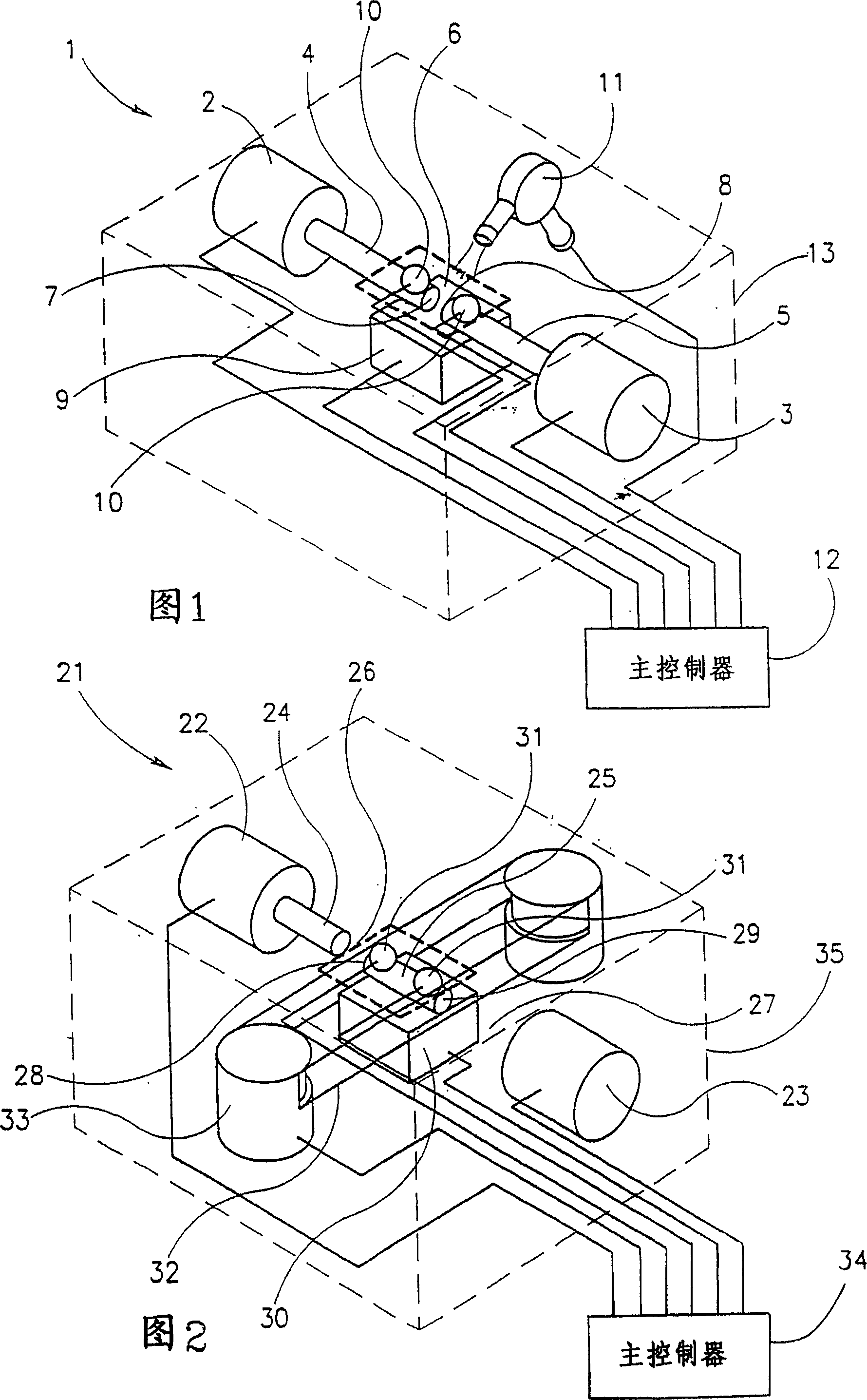
[0078] Referring first to Figure 1, there is shown a first alternative dew point hygrometer 1 according to the present invention. The hygrometer includes a light emitter 2, such as a HFBR-1524 emitter (Hewlett Packard Components, USA), and a light detector 3, such as a HFBR-2524 receiver (Hewlett Packard Components, USA). The light emitter 2 and the light detector 3 are coupled via an optical path defined by two optical fibers: a first optical fiber 4 coupled to the light emitter and a second optical fiber 5 coupled to the light detector. The optical fibers 4 and 5 are separated from each other so that a detection gap 6 is formed therebetween. The optical fiber is a Hewlett Packard plastic fiber optic cable HFBR-PUS001 with a diameter of 1.0 mm (Hewlett Packard Components, USA). The unconnected end 7 of the first optical fiber and the unconnected end 8 of the second optical fiber serve as exposed forming ends. These ends are in contact with the gas whose dew point is to be d...


PUM

PropertyMeasurementUnit
thicknessaaaaaaaaaa
diameteraaaaaaaaaa

Abstract

The invention concerns dew point hygrometers based on condensation of dew on ends of optical fibers, or on surfaces of an optical prism. The invention also concerns a dew sensor for determining the natural dew condensation by optical means and a dew sensor capable of detecting dew by detecting a change in capacitance.

Description

[0001] This application is a divisional application of an invention patent application with the application number 99813909.2, the application date being October 29, 1999, and the invention title being "dew point hygrometer and dew detector". technical field [0002] The invention relates to a dew point hygrometer for determining the dew point of a gas and a dew detector for determining the condensation of neutral dew. More specifically, the present invention relates to hygrometers comprising optical fibers, or hygrometers based on changes in capacitance. Background technique [0003] Existing hygrometers used in agriculture, especially in greenhouses, are no more than the following three types. The first is a high maintenance psychrometer. The second type is the relative humidity meter, whose operating principle is based on a change in capacitance, which often fails at high relative humidity. Inexpensive instruments based on capacitance measurements are unreliable because...

Claims


Application Information

Patent Timeline
Patent Type & Authority Applications(China)
IPC IPC(8): G01N21/47G01N21/17G01N21/41G01N25/68G01N27/22G01W1/11
CPCG01N25/68
Inventor 埃格·兹乐金
Owner OPTIGUIDE
Why Eureka
Try Eureka