
Lamp unit and display device of projector system

A technology of a display device and a lamp unit, applied in the field of projector systems, can solve the problems of increased manufacturing cost, troublesome and complicated formation of a reflective film, etc.

Inactive Publication Date: 2005-08-24
SAMSUNG ELECTRONICS CO LTD
View PDF0 Cites 8 Cited by
  • Summary
  • Abstract
  • Description
  • Claims
  • Application Information

AI Technical Summary

Problems solved by technology

[0016] However, forming a reflective film near the electrode welding portion 29 of the lamp 20 of the lamp unit 10 is a very troublesome and complicated process.
Then, the manufacturing cost of the lamp unit 10 increases

Method used


Image

  • Lamp unit and display device of projector system
  • Lamp unit and display device of projector system
  • Lamp unit and display device of projector system

Examples


Embodiment Construction

[0031] Hereinafter, exemplary embodiments of the present invention will be described in detail with reference to the accompanying drawings.

[0032] In the following description, the same reference numerals identify the same elements even in different drawings. The matters defined in the description, such as the detailed construction and elements, are merely an aid to a comprehensive understanding of the invention. Therefore, it is apparent that the present invention can be carried out without those defined matters. Also, for well-known functions and constructions, they are not described in detail since their unnecessary repetition would obscure the invention.

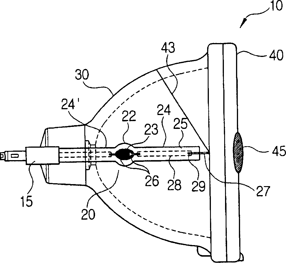
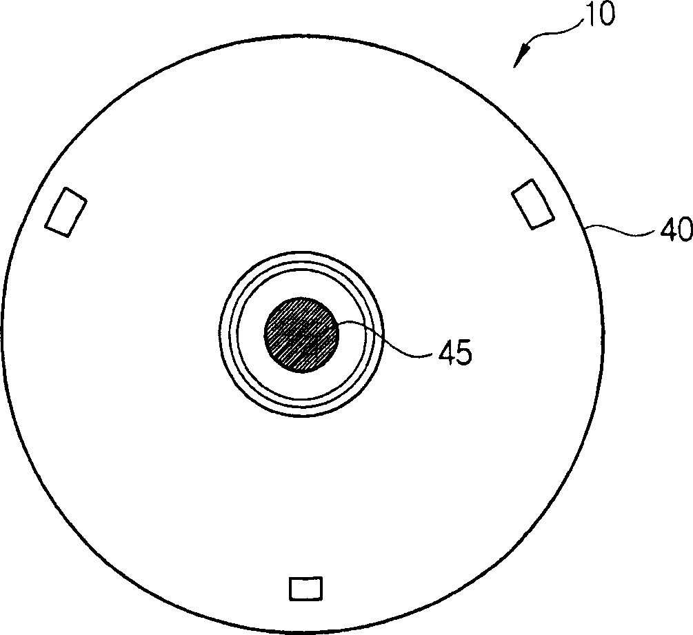
[0033] refer to figure 2 and 3 , the lamp unit 10 includes: a lamp 20, the lamp 20 is installed in the reflector 30; a protective glass cover 40, which is arranged at the opening of the reflector 30, to prevent the lamp 20 from scattering when it is broken; and a light blocking member Or blocking means 45.

[003...


PUM


Abstract

A lamp unit of a projector system and a display device using the same, includes a lamp; a reflector for reflecting a light generated from the lamp; and a cover glass mounted at an opening of the reflector, and the cover glass having a blocking device for obstructing a light incident from an optical system, disposed in front of the light with respect to a light projecting direction, to the reflector. Accordingly, a light irradiated to the lamp, which increases the temperature of an electrode welding part of the lamp, can be blocked, thereby improving a lifespan of the lamp.

Description

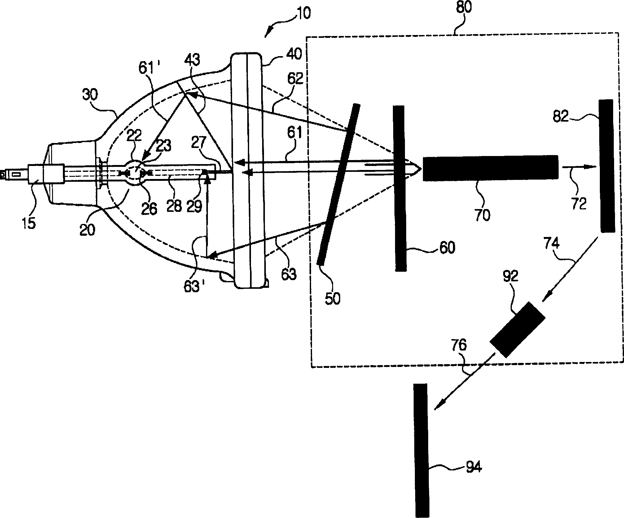
technical field [0001] The present invention relates to a projector system, and more particularly, an apparatus according to the present invention relates to a lamp unit for a digital light processing (DLP) or liquid crystal display (LCD) projector system and a display device using the lamp unit. Background technique [0002] Recently, a digital light processing (DLP) projector or a liquid crystal display (LCD) projector using a digital micromirror display (DMD) panel is widely used in a wide-screen image projection system. [0003] figure 1 is a schematic diagram of a conventional DMD projector system including lamp unit 10 and projection system 80 . [0004] The lamp unit 10 has the lamp 20 installed in the reflector 30 and the protective glass cover 40 provided at the opening of the reflector 30 to prevent the lamp 20 from being scattered in case the lamp 20 is broken. [0005] The optical system 80 includes: an ultraviolet (UV) filter 50 for blocking ultraviolet rays g...

Claims


Application Information

Patent Timeline
Patent Type & Authority Applications(China)
IPC IPC(8): G03B21/20F21V13/10G03B21/00H04N9/31
CPCH04N9/3197H04N9/3114H04N9/315A61H23/0263A61H2201/5043A61H2201/5097A61H2205/082
Inventor 陈连植郑明烈李尚洙
Owner SAMSUNG ELECTRONICS CO LTD
Learn More