Device and program for monitoring computer mainframe and power supply

A computer case and power supply technology, applied in hardware monitoring, sustainable buildings, energy-saving computing, etc., can solve problems such as noise, no speed adjustment, and inability to monitor operating status, and achieve the effect of reducing noise

Inactive Publication Date: 2005-08-24
李谦
View PDF0 Cites 12 Cited by
  • Summary
  • Abstract
  • Description
  • Claims
  • Application Information

AI Technical Summary

Problems solved by technology

[0006] Although the prior art has had the above-mentioned various developments, the monitoring of equipment in the computer case is limited to the monitoring circuit on the computer motherboard, and the monitoring of other equipment in the case is not solved, such

Method used


Image

  • Device and program for monitoring computer mainframe and power supply
  • Device and program for monitoring computer mainframe and power supply
  • Device and program for monitoring computer mainframe and power supply

Examples


Embodiment 2

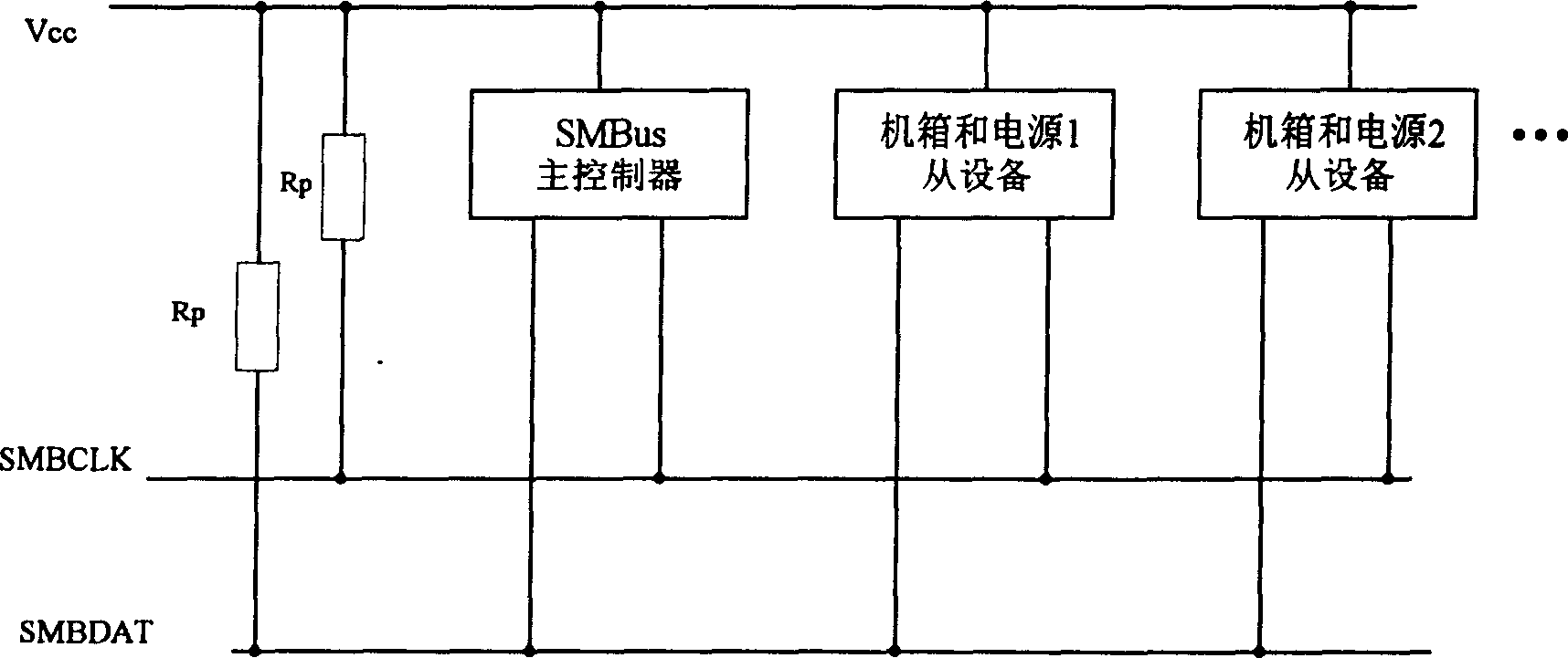
[0062] Embodiment 2. The circuit principle of the present embodiment is as Fig. 5, and the present embodiment computer uses ATX power supply and 915 / 925 series motherboard, at first in Figure 7 On the expansion board of the computer, the present embodiment sets the SMBus interface expansion device on the PCI ExpressX1 board, and the SMBus interface expansion device is formed as Figure 7 As shown in 13, the SMBus interface expansion device has 4 pins: SMBCLK, SMBDAT, power supply Vcc, ground GND and a positioning gap. The SMBus clock line SMBCLK and data line SMBDAT are drawn from B5 and B6 of the computer board slot. In this embodiment, Vcc=3.3V is drawn from B8 of the board slot, and G is drawn from B7 of the board slot.

[0063] From the computer PCI ExpressX1 board through the SMBus interface expansion device, lead SMBDAT and SMBCLK to the computer power monitoring circuit, connect the SMBus of the monitoring chip to the SMBDAT and SMBCLK of the circuit LM85. The monitor...

Embodiment 4 example pic 6,6,5,SMBus and ,12V,,T。 example 1 and pic 3, example PCISMBus, to ,SMBus pic 713,SMBus4:SMBCLK、SMBDAT、Vcc、GND and 1 ,SMBusSMBCLK and SMBDATPCIA40、A41, example Vcc=3.3V。 Embodiment 5

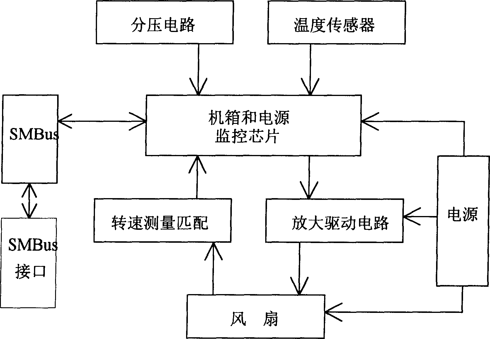
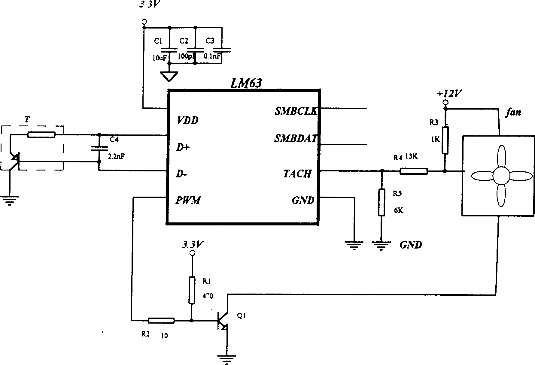
[0079] Embodiment 4 In this example, the monitoring circuit is installed in the expansion bracket of the computer case as Figure 6 , of which 6 is the bracket fan, 5 is the bracket monitoring circuit board, on which there are SMBus chips and peripheral components, the 12V power supply is obtained through the computer power extension plug, the heating device is the device on the bracket such as a hard disk, and the temperature sensor T is close to it. above it. Using Example 1 and image 3 Described circuit, in this example, the SMBus interface is set on the PCI board, and connected to the bracket monitoring circuit board, the SMBus interface is composed as follows Figure 7 As shown in 13, the SMBus interface has 4 pins: SMBCLK, SMBDAT, power supply Vcc, ground GND and a positioning gap. The SMBus clock line SMBCLK and data line SMBDAT are drawn from A40 and A41 of the PCI board slot. In this example In Vcc=3.3V. Example 5: Use the circuit shown in Figure 5 in combination ...


PUM


Abstract

A device and process which will monitor the computer's shell and electric source, and it relates to the expansion of SMBus and the use of SMBus slug. The device can be set in the electric source unit and/or on the expansion board. Then it will use the monitor circuit to measure the voltage, the temperature and the speed of rotation of the fan in the shell and the device in the power. After that, it will input the temperature value as feedback signal into SMBus slug. The slug will output the calculated value and after the value is enlarged, it can control the speed of rotation to become a closed loop. The SMBus, the PCI Express board, The PCI board and the PCI-X board are linked to the SMBus interface on the king plank. The positive effect is that intelligent shell and power can be made up to make the computer have no noise to save energy. Besides, through the communication of SMBus and the host computer, the application program can monitor the running state in real time, so it does good to administrating the computer's system device.

Description

technical field [0001] The invention relates to computer system management bus (SMBus) expansion and the application of components thereof, including a device and a program for monitoring a computer case and a power supply by using a system management bus chip to form a circuit. Background technique [0002] Computer case and power supply Computer case is an important accessory of the computer. The common forms are ATX and BTX, while the computer server case is larger, and all of them are equipped with motherboard, CPU, memory, display card, hard disk, optical drive and other equipment, or extended SCSI , I / O acquisition board, etc. Due to the high heat generation of the computer, the chassis is usually ventilated and cooled by a fan. One of the devices in the chassis is the computer power supply, which inputs 220V / 110V AC power supply, and outputs energy to the computer after rectification and filtering, PWM control, voltage stabilization and protection circuits, etc. Ther...

Claims


Application Information

Patent Timeline
IPC IPC(8): G06F11/30G06F11/32
CPCY02B60/165Y02D10/00
Inventor 李谦
Owner 李谦
Why Eureka
Try Eureka