
X-ray apparatus

A technology of X-ray and high-voltage devices, applied in X-ray equipment, electrical components, etc.

Active Publication Date: 2005-08-24
富士胶片医疗健康株式会社
View PDF2 Cites 16 Cited by
  • Summary
  • Abstract
  • Description
  • Claims
  • Application Information

AI Technical Summary

Problems solved by technology

In this way, with regard to the X-ray high-voltage device, the problem of balancing the performance aspects such as a wide output range with the reduction of the installation area, size reduction, and weight reduction has remained unsolved until now.

Method used


Image

  • X-ray apparatus
  • X-ray apparatus
  • X-ray apparatus

Examples


Embodiment Construction

[0033] The best way to practice the invention

[0034] Embodiments of the present invention will be described in detail below with reference to the accompanying drawings.

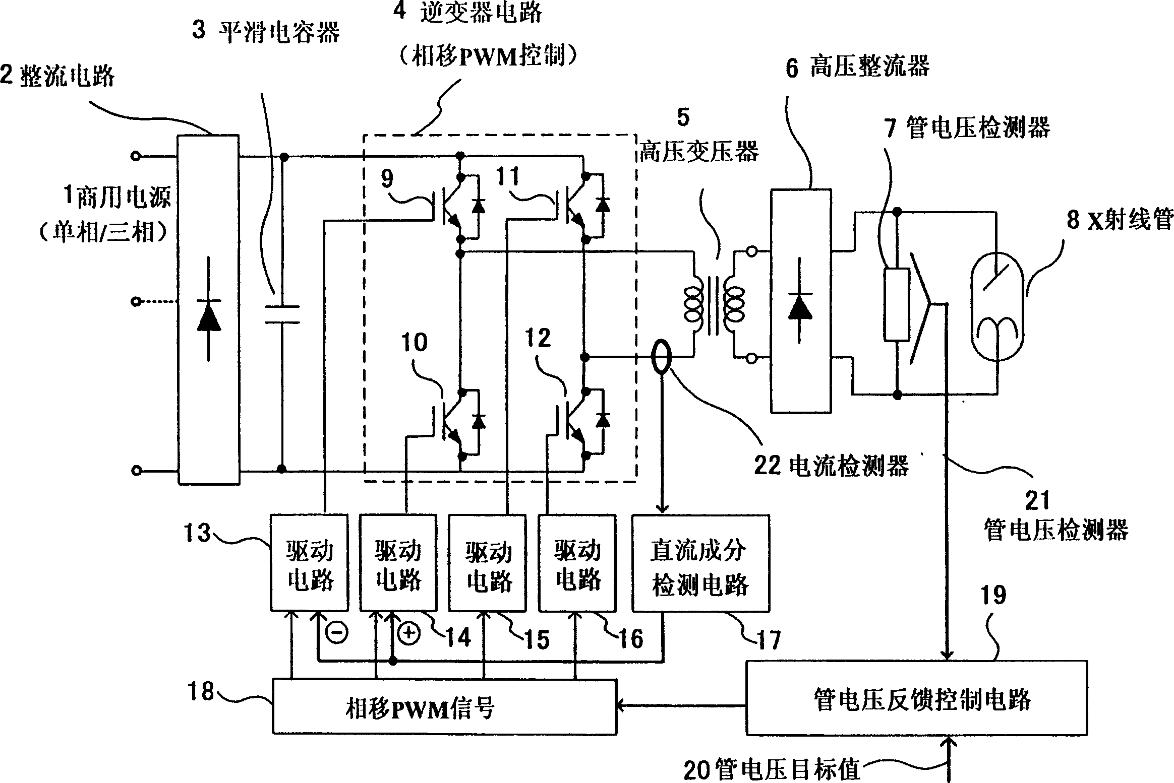
[0035] In the figure, 1 is a commercial power supply, 2 is a rectifier circuit, 3 is a smoothing capacitor, 4 is an inverter circuit, 5 is a high-voltage transformer, 6 is a high-voltage rectifier, 7 is a tube voltage detector, 8 is an X Ray tube, 9-12 are semiconductor switching devices, 17 is a DC component detection circuit, 18 is a phase shift PWM signal circuit, 19 is a tube voltage feedback control circuit, 22 is a current detector.

[0036] figure 1 It is a circuit block diagram showing an inverter type X-ray high voltage device according to one embodiment of the present invention. A rectification circuit 2 is connected to a three-phase or single-phase commercial power supply 1 , and a smoothing capacitor 3 is connected to an output side of the rectification circuit 2 . An inverter circuit 4 havin...


PUM


Abstract

An inverter system X-ray high-voltage apparatus which controls a lamp voltage by the phase shift PWM control of a semiconductor switching device changes the time ratio of the phase shift PWM signal inputted to a driver circuit of the semiconductor switching device to correct this DC component when a DC component detecting circuit with the controlled lamp voltage detects the DC component of an output of an inverter circuit via a current detector provided on the primary side of a high-voltage transformer, corrects an output voltage from the inverter circuit into a positive-negative symmetric waveform to eliminate a bias magnetism in the high-voltage transformer, enables the size of the high-voltage transformer and the omission of a DC / DC converter, and enables the reduction in set-up area, size, and weight, and an X-ray apparatus comprising this apparatus.

Description

technical field [0001] The present invention relates to an inverter type X-ray high-voltage device that converts DC voltage into high-frequency AC voltage by an inverter circuit, and applies the output AC voltage to an X-ray tube through a transformer, and an X-ray device using it. Background technique [0002] Recently, general X-ray imaging equipment, circulator X-ray imaging equipment, and X-ray CT equipment have been widely applied to medical X-ray high-voltage equipment. The requirement for these X-ray high-voltage devices is to be able to provide the required tube voltage stably. On this basis, recently, in order to increase the width of the tube voltage output range and the degree of freedom of setting, so as to be able to cope with various devices, it is necessary to reduce the setting There is an increasing demand for reduced area and size and reduced weight. [0003] For example, JP-A-9-190898 discloses an inverter-type X-ray high voltage device using pulse modula...

Claims


Application Information

Patent Timeline
IPC IPC(8): H05G1/32H05G1/10H05G1/20
CPCH05G1/10
Inventor 菱川真吾堂本拓也高野博司
Owner 富士胶片医疗健康株式会社
Learn More