

Flap valve and flap filter tank
A flap filter and valve technology, applied in the direction of filtration separation, gravity filter, loose filter material filter, etc., can solve the problems of flap valve and flap filter not tightly sealed, easy to lose filter material, etc. Achieve the effect of large specificity, high backwashing intensity and good pollution interception ability
- Summary
- Abstract
- Description
- Claims
- Application Information
AI Technical Summary
Problems solved by technology
Method used
Image

Examples
Embodiment Construction
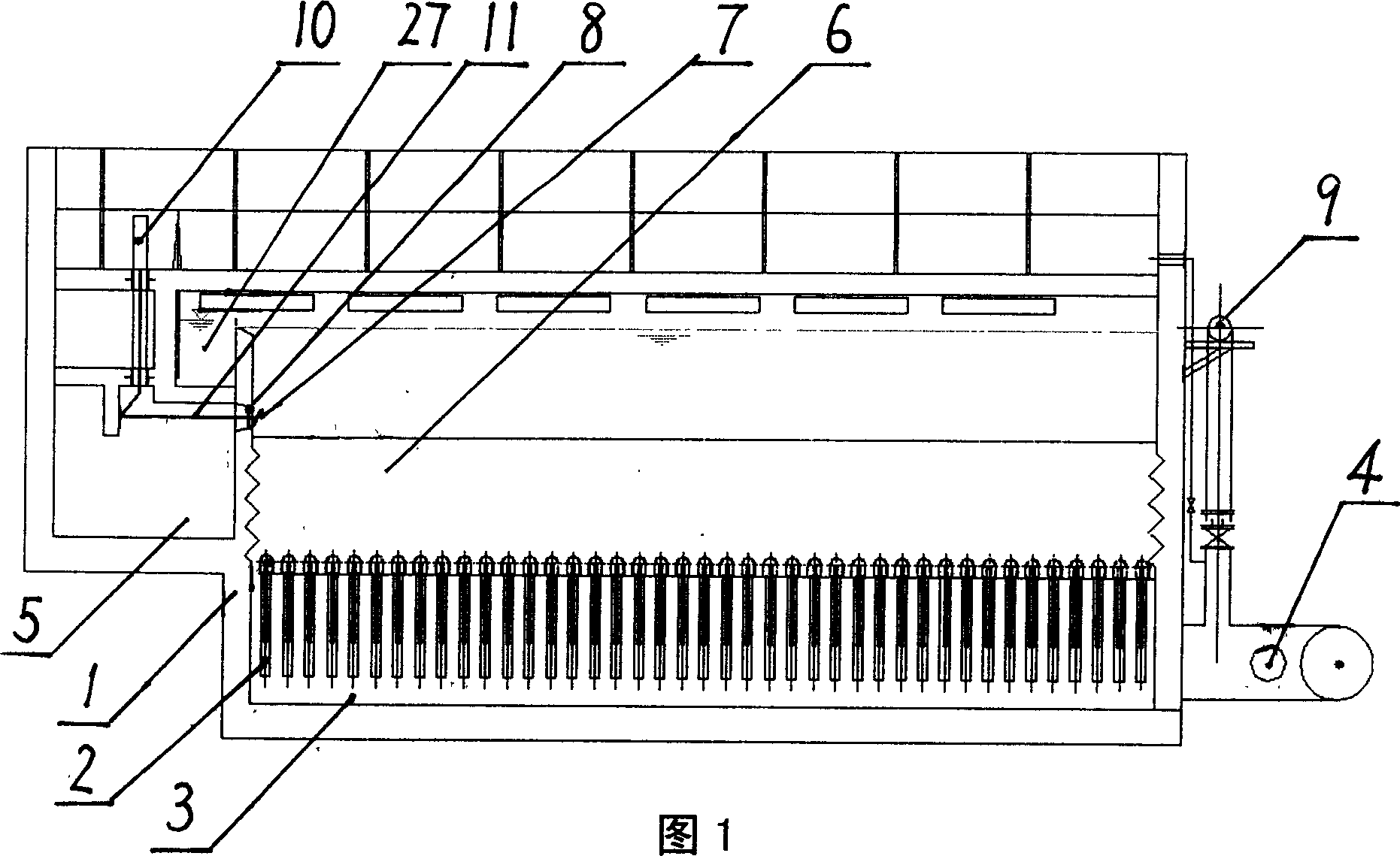
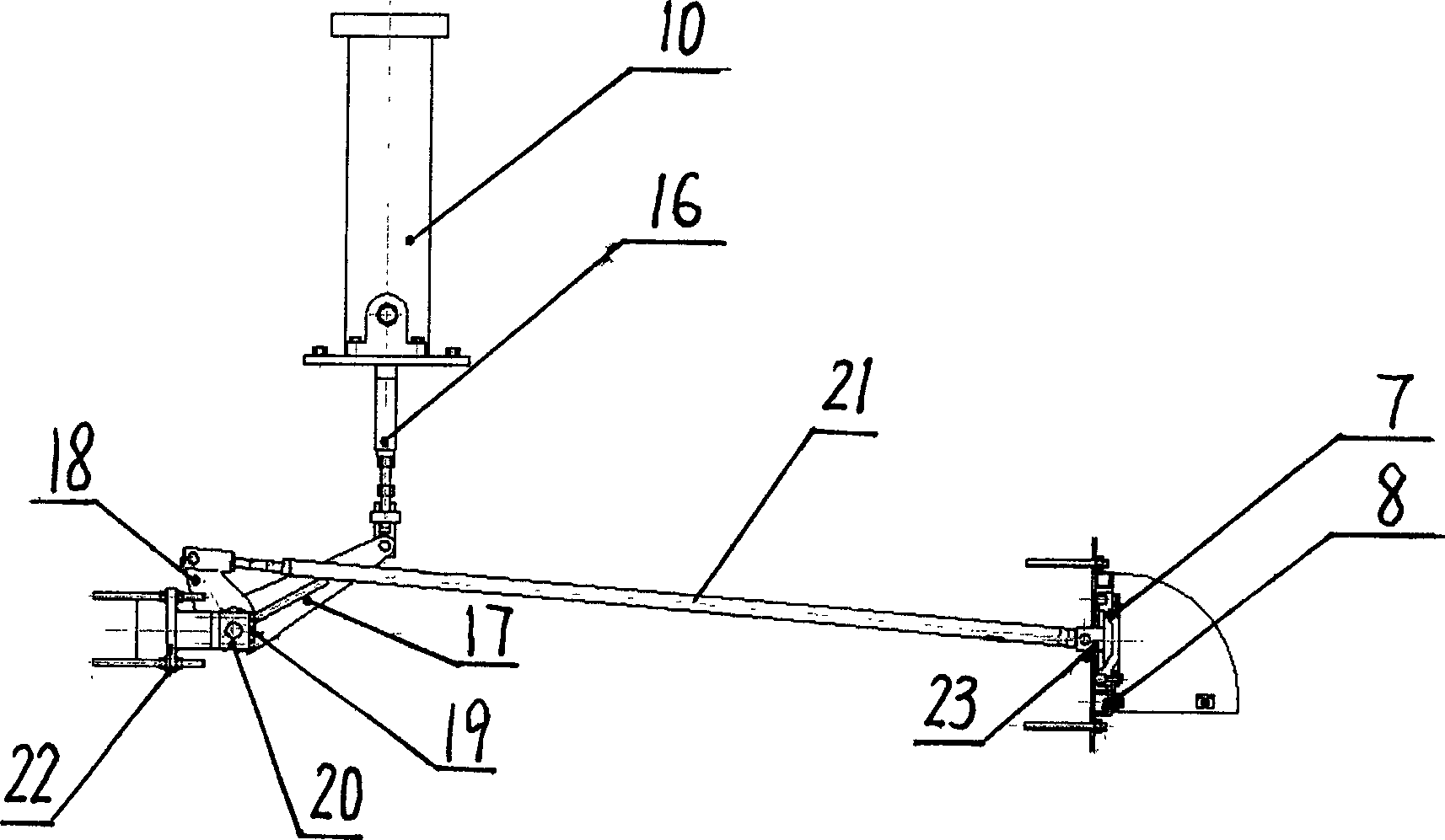
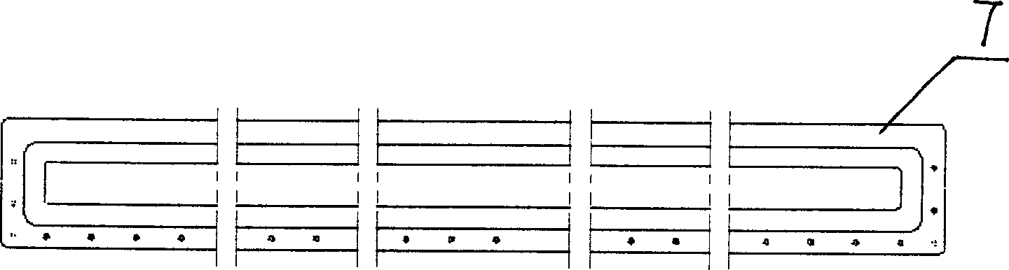
[0033] Refer to Figure 1 for the embodiment of the flap filter. This flap filter is equipped with a filter tube 2 at the bottom of the pool body 1, and a water collection chamber 3 is provided at the bottom of the pool body 1. The water collection chamber and the filtered water outlet pipe 4 communicates with the recoil pipe 9, and the filter material layer 6 is arranged inside the pool body 1, and the recoil drainage channel 5 and the overflow weir 27 are connected to the outside of the pool wall relative to the filter material layer, and the recoil drainage channel 27 is connected to the filter tank and the recoil drainage channel A flap valve is installed at the hole 32 of the hole for recoil drainage. The valve frame 8 is fixed on the hole 32, the lower side of the valve plate 7 is hinged with the valve frame 8, and the middle part of the valve plate is hinged with the driving mechanism. The driving mechanism includes a driving cylinder 10 And the push-pull connecting rod 1...
PUM
 Abstract
Description
Claims
Application Information