Flux integrating instrument of iterating differential pressure

A flow totalizer and iterative technology, applied in the field of flow totalizers, can solve problems such as unsolvable errors and no real-time performance, and achieve the effect of improving range ratio and low cost

Inactive Publication Date: 2005-08-31
张国仁
View PDF0 Cites 6 Cited by
  • Summary
  • Abstract
  • Description
  • Claims
  • Application Information

AI Technical Summary

Problems solved by technology

At present, the iterative method is used, which requires manual operation of computers or calculators, so the

Method used


Image

  • Flux integrating instrument of iterating differential pressure
  • Flux integrating instrument of iterating differential pressure
  • Flux integrating instrument of iterating differential pressure

Examples


Example Embodiment

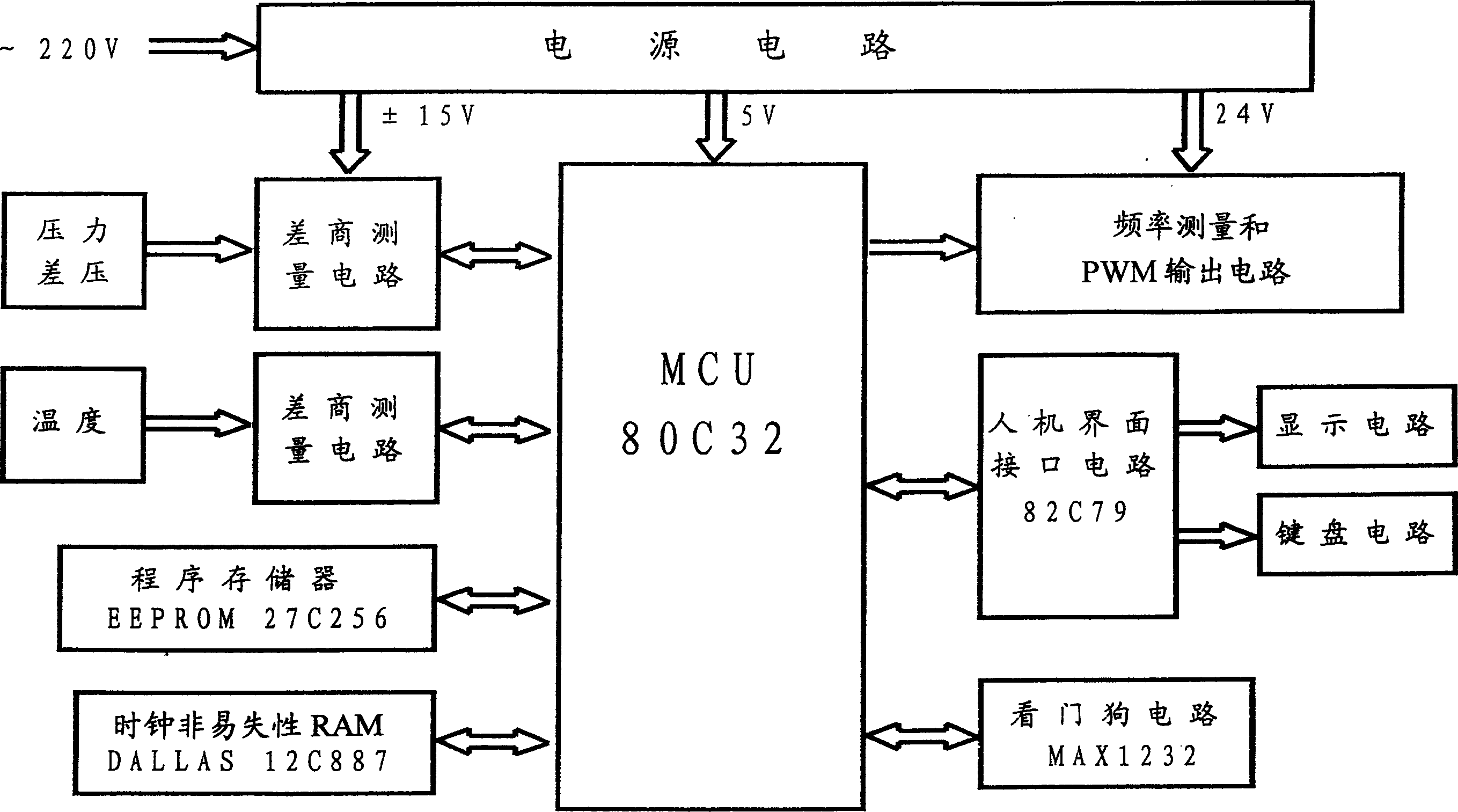
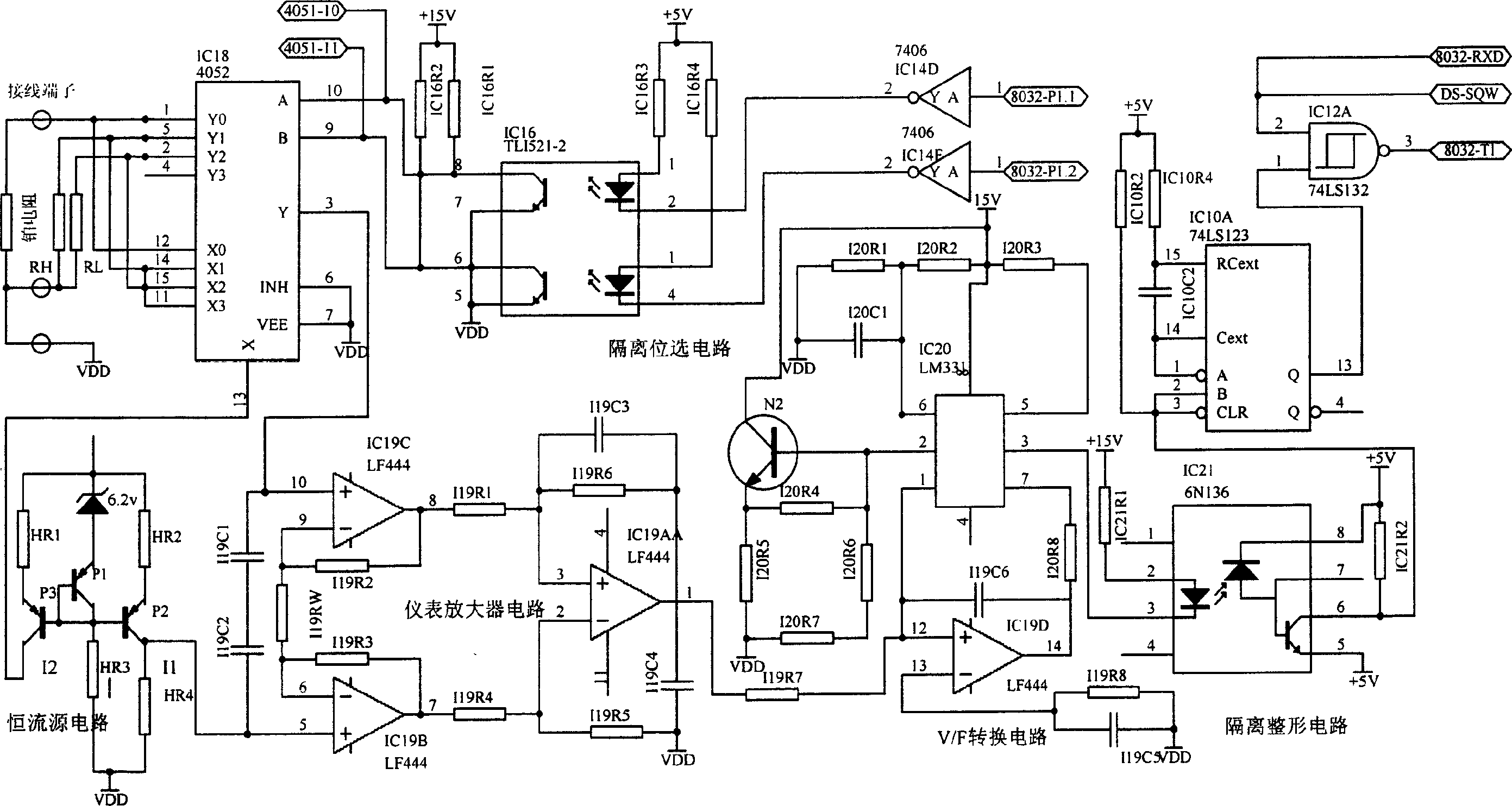
[0026] The function of the platinum resistance difference quotient measurement circuit is to measure the temperature of the measured medium, and the purpose of measuring the temperature is achieved by measuring the resistance of the platinum resistance. This temperature is used to look up the table to calculate the density of the measured medium, as well as the pipe diameter D, the opening diameter d of the throttling element and the diameter ratio β under working conditions.

[0027]The measured platinum resistance RT from the outside is connected to the meter terminal in a three-wire system, and then connected to the analog switch circuit by the internal connection similar to the internal standard resistance RH and RL. When working, the P1.1 and P1.2 ports of the single-chip microcomputer control the position selection terminals A and B of the 4052 through the driver 7406 and the photocoupler TLP521-2, and connect the constant current source I1 to RH, RL and Rt in turn to genera...


PUM


Abstract

The present invention relates to a flow integrating instrument, specially, it is a differential pressure interative flow integrating instrument. It is formed from platinum resistance difference quotient measuring circuit; pressure and differential pressure difference quotient measuring circuit; PWM output circuit; keyboard and displaying circuit; power supply circuit and microcontroller circuit. Said invention also provides its application range.

Description

technical field [0001] The invention relates to a flow totalizer, in particular to a differential pressure iterative flow totalizer. Background technique [0002] The throttling device is a set of devices for generating a static pressure difference in the fluid flowing in the pipeline. It consists of three parts: a throttling element, a pressure taking device and a straight pipe section that meets the requirements. The throttling element is obtained by mechanical processing to make the fluid shrink and have different shapes, and there are three forms of orifice plate, nozzle, and Venturi tube. The orifice plate is a circular thin plate, the nozzle is a cylindrical body that smoothly forms a throat, and the Venturi tube is a cylindrical short tube that smoothly forms a throat and diffuses smoothly. The pressure taking device is a set of equipment for measuring the pressure difference before and after the throttling element in a certain way. It is divided according to the dis...

Claims


Application Information

Patent Timeline
IPC IPC(8): G01F1/36
Inventor 张国仁安树祥
Owner 张国仁
Why Eureka
Try Eureka