Multiple drive conveyor system

A conveyor, motion technology, applied in the direction of conveyors, conveyor objects, transportation and packaging, etc., can solve the problems of difficult maintenance, cleaning and cleaning of the system

Inactive Publication Date: 2005-08-31
GARVEY CORP
View PDF0 Cites 0 Cited by
  • Summary
  • Abstract
  • Description
  • Claims
  • Application Information

AI Technical Summary

Problems solved by technology

Such a large system is also difficult to maintain, clean and clean

Method used


Image

  • Multiple drive conveyor system
  • Multiple drive conveyor system

Examples


Embodiment Construction

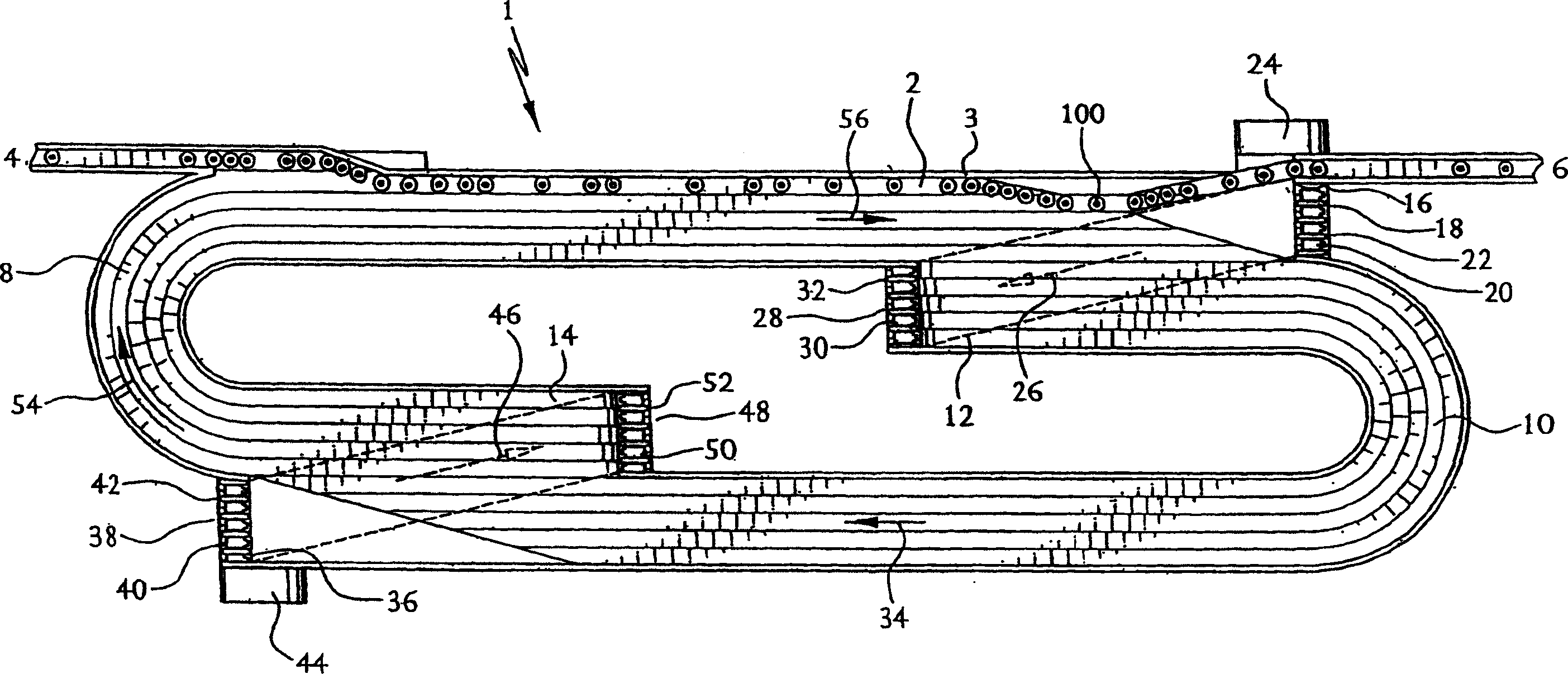
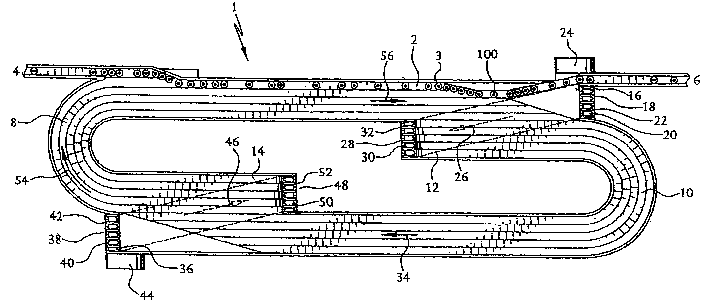
[0025] The conveyor system 1 comprises a single loop continuous path conveyor 2, which can be installed on the ground, for example on a raised frame 3, as is commonly used in the industry. The conveyor 2 is configured to move and accumulate products, such as bottles 100, from the upstream position marked 4 to the downstream position marked 6. The conveyor 2 includes product carrying sections 8, 10 and offset return path sections 12, 14. It is envisaged that these sections of the conveyor 2 can be configured as interlocking chain sections, as is well known in the art. The sections 8, 10, 12 and 14 form the continuous conveyor 2. All these conveyor sections are located in the same transverse plane.

[0026] When the chain sections constituting the product carrying section 8 reach the position marked 16, they are connected to the drive sprocket assembly 18, which includes a bearing support shaft 20 supporting the sprocket 22. The shaft 20 is mechanically connected to a power unit, su...


PUM


Abstract

A conveyor system which comprises a continuous path conveyor is to be used f or transporting and accumulating excessive loads. The conveyor may be formed of a continuous loop of chain elements (8). The conveyor path consists of two or more product carrying sections (10, 54, 34) and corresponding offset return path sections (26, 24). A product carrying section of the conveyor wraps around power driven sprockets (16, 18, 20,22) where it is fed into and becom es a return path section. From there the path is guided over and aligned with free turning tail sprockets, where it is returned as a product carrying section. This section is then fed onto second drive sprockets,(38, 40, 42), powered by another power means (44), where it again becomes a return path seciton, guided over tail sprockets and returned as a product carrying section. In this manner, the load of the conveyor chain is relieved at each drive sprocket assembly, thereby increasing the available working distance o f the system.

Description

Background technique [0001] Conveyor systems are generally used to process and transport products located in confined physical spaces and between upstream and downstream destinations in remote sections of the facility. This system, which moves products over long distances, especially heavy products, is subjected to excessive load forces during transportation. In addition, a product stacking system that is usually used in combination with a conveyor to store and stack products uses a conveyor and a conveyor system. Depending on the load and the number of products that can be stacked, the stacking system also withstands excessive weight from the conveying load. [0002] During normal processing, systems with long product conveying surfaces and product stacking devices experience considerable loads during normal operation. When the processed product starts to be heavy, the conveyor surface is subjected to additional excessive force. It is very important to assume that the working str...

Claims


Application Information

Patent Timeline
IPC IPC(8): B65G23/08B65G23/36B65G47/51
CPCB65G47/5145B65G23/36
Inventor M·C·加维
Owner GARVEY CORP
Why Eureka
Try Eureka