Rotary machine

一种旋转电机、旋转轴的技术,应用在旋转电机的定子,车辆用交流发电机领域,能够解决制造工序复杂、增加导体、复杂化等问题,达到制作容易、降低高次谐波成分、工艺的简化的效果

Inactive Publication Date: 2005-09-07
HITACHI LTD
View PDF2 Cites 32 Cited by
  • Summary
  • Abstract
  • Description
  • Claims
  • Application Information

AI Technical Summary

Problems solved by technology

However, in the above-mentioned winding configuration, the types of conductors must be increased to arrange conductors in adjacent slots, so the complexity becomes complicated, and the manufacturing process also becomes complicated accordingly.

Method used


Image

  • Rotary machine
  • Rotary machine
  • Rotary machine

Examples


Embodiment 1

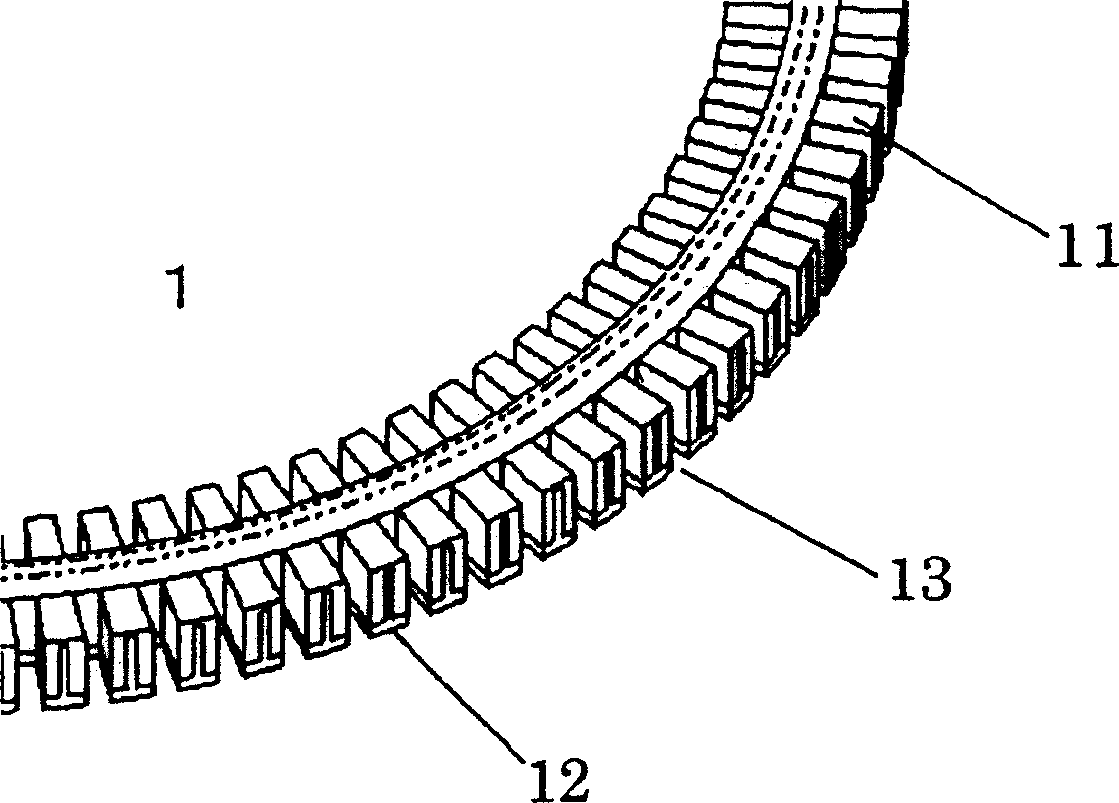
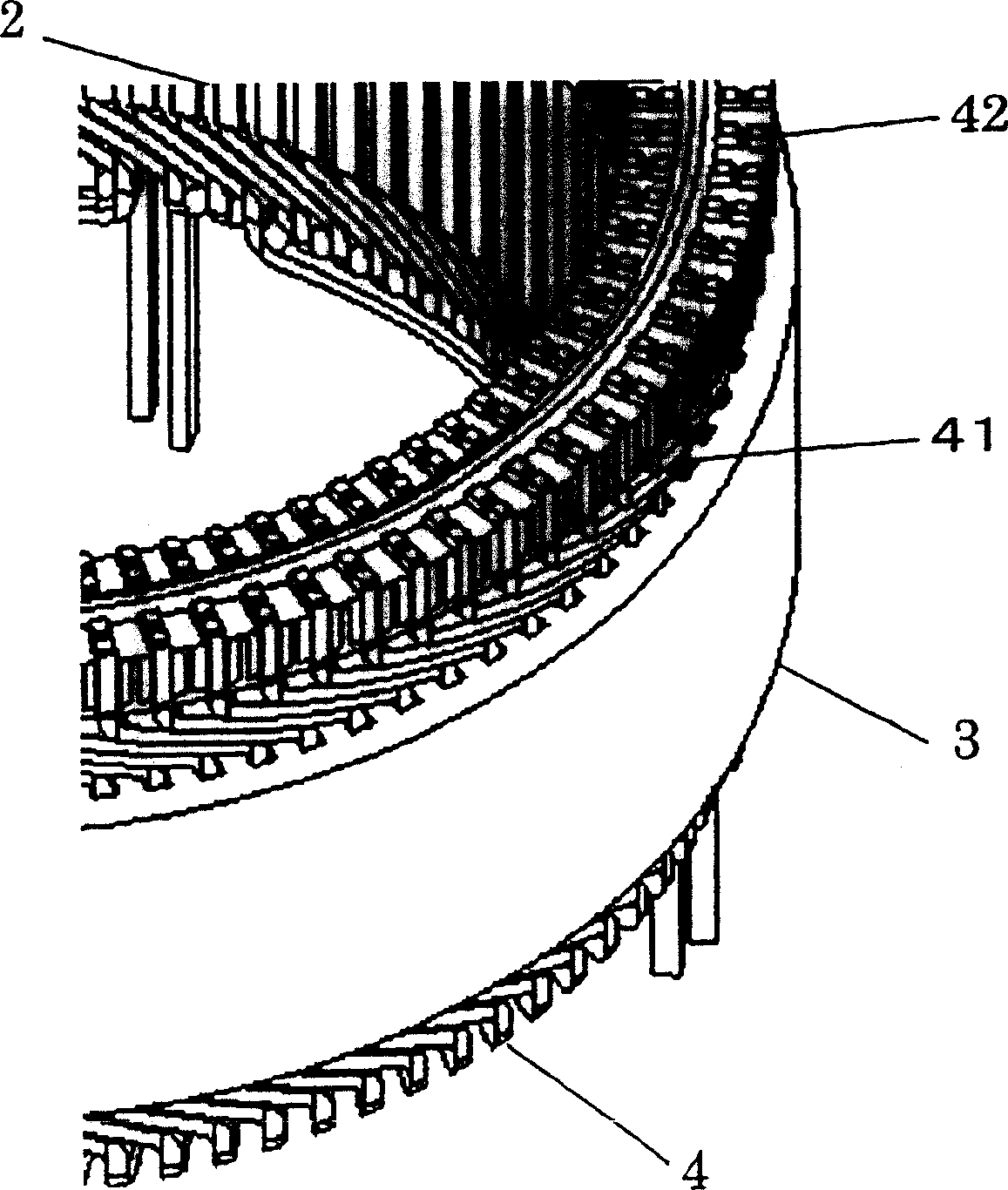
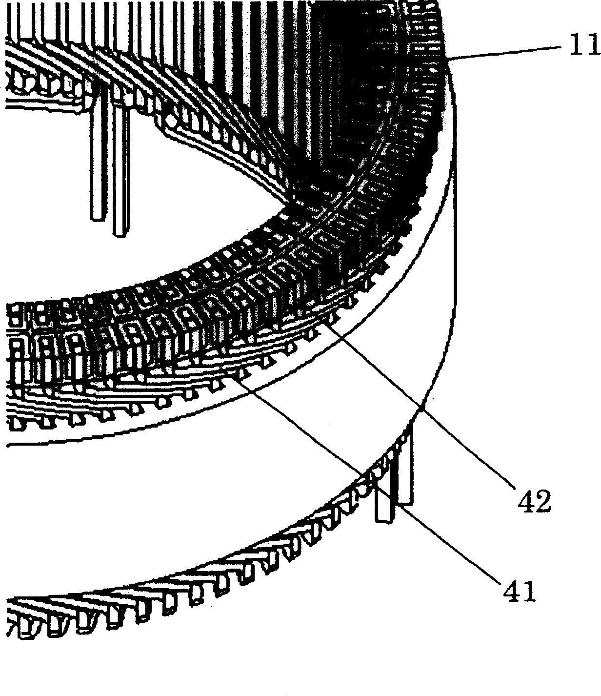
[0056] Example 1 will be described. Figure 1 shows an enlarged view of the connecting ring used in this embodiment, Figure 2 shows an enlarged view of the assembled state of the connecting ring, Figure 3 shows an enlarged view of the state after the connecting ring is divided, and Figure 4 shows a state diagram of the connecting ring after dividing. 1 to 4 above show an example in which the number of slots is 90, and each slot has four conductors.

[0057] In FIG. 1 , a connection ring 1 is composed of a conductor portion 11 and an insulating portion 12 . The connection ring 1 has a plurality of grooves 13 corresponding to the number of connection points of the terminal portions 42 of the plurality of conductors 41, and an insulating portion 12 is arranged between the plurality of grooves 13 and adjacent grooves 13 to ensure a uniform insulation. Since four conductors are arranged in one slot, and the No. 1 and No. 2 of the end portion 42 counted from the outer peripheral si...

Embodiment 2

[0060] Example 2 will be described. In FIG. 5 , which is an enlarged view showing a state after being connected by reversely twisted conductors, an example in which the number of slots is 90 and 4 conductors per slot is shown. Since each slot is equipped with 4 conductors, the phase winding consists of: an outer circuit 6 composed of a plurality of No. 1 and No. 2 conductors 41 counted from the outer peripheral side, and a plurality of No. 3 and No. The inner circuit 7 composed of two conductors 41 is formed by connecting the tail end conductor 46 of the outer circuit and the head end conductor 48 of the inner circuit. The connection of the tail end conductor 46 of the outer circuit and the head end conductor 48 of the inner circuit can be canceled by using the anti-twisted conductor 43 .

Embodiment 3

[0062] Example 3 will be described. Figure 6 is an enlarged view of the state of connecting conductors with different pitches, showing that the number of poles is 12, the number of slots is 90, the number of phases of the stator winding is 3, and the number of slots per pole and phase determined according to the number of poles is 2.5, An example of a winding circuit with 5 conductors per pole and 4 conductors per slot.

[0063] In this winding circuit, 4 conductors per slot are arranged in a row along the diameter direction, and are divided into the first and second conductors and the third and fourth conductors counted from the outer peripheral side. The outer circuit 6 constituted by two conductors and the inner circuit 7 constituted by the third and fourth conductors of the plurality of slots are constituted by a combination.

[0064]In the outer circuit 6, 15 slots are arranged corresponding to each pair of magnetic poles of the rotor (a pair of magnetic poles of N pole ...


PUM


Abstract

A rotary machine comprising a stator 2 composed of a stator iron core 3 having a plurality of slots formed in the direction of the rotation axis and stator windings inserted into the plurality of slots, wherein the stator windings are composed of a plurality of conductors 4 respectively inserted into the plurality of slots in the direction of the rotation axis and the stator 2 has a connection ring 1 having slots 13 into which the plurality of conductors 4 are inserted in the direction of the rotation axis.

Description

technical field [0001] The present invention relates to a rotating electrical machine, in particular to a stator of a rotating electrical machine such as an alternator for a vehicle which is driven by an internal combustion engine to generate electric energy for an on-vehicle electric load or an on-vehicle power supply. Background technique [0002] Conventionally, patent document 1 and patent document 2 are known as methods for connecting terminal portions of stator conductors of rotating electric machines. In the manufacturing method in Patent Document 1, a holder is disposed between two adjacent conductor end portions in the circumferential direction so as to be in contact with the conductor end portions on both sides, and holds a plurality of the conductor end portions; The leading end portions are joined while holding a plurality of the conductor end portions; after the joining, the holder is moved and released. The joining method used in Patent Document 2 is to carve ...

Claims


Application Information

Patent Timeline
Patent Type & Authority Applications(China)
IPC IPC(8): H02K3/04H02K3/12H02K3/28H02K3/38H02K3/46H02K3/50
CPCH02K3/50H02K3/505H02K3/12H02K2203/09
Inventor 森嘉己植田俊明酒井毅木村康彦小野濑伸金泽宏至本间雅彦
Owner HITACHI LTD
Why Eureka
Try Eureka