Trans-critical refrigerating unit

A refrigeration device, transcritical technology, applied in the direction of refrigerators, components of pumping devices for elastic fluids, refrigeration components, etc., to achieve the effect of suppressing sliding loss and suppressing leakage loss

Inactive Publication Date: 2005-09-21
SANYO ELECTRIC CO LTD
View PDF2 Cites 4 Cited by
  • Summary
  • Abstract
  • Description
  • Claims
  • Application Information

AI Technical Summary

Problems solved by technology

[0006] The purpose of the present invention is to solve various existing problems and provide a transcritical refrigeration device that can suppress the occurrence of sliding loss and leakage loss as much as possible and can obtain the maximum COP

Method used


Image

  • Trans-critical refrigerating unit
  • Trans-critical refrigerating unit
  • Trans-critical refrigerating unit

Examples


Embodiment 1

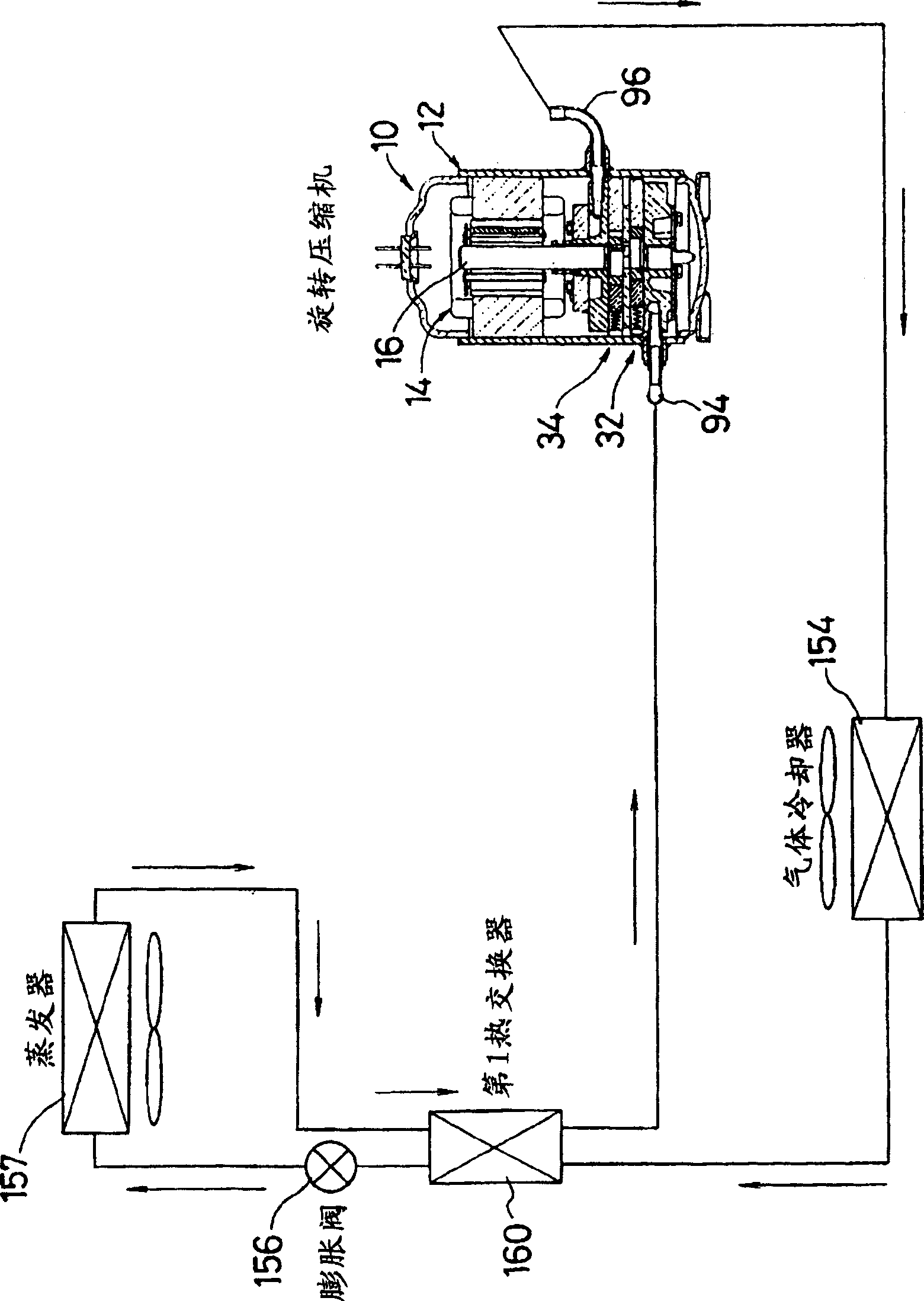
[0075] When used with Figure 4 The transcritical refrigeration device of the present invention of the refrigerant circuit shown in 2 ) was used as the refrigerant, and the lubricating oil listed in Table 1 was used, and the test operation was carried out under the two-stage compression condition of 9 MPa on the high pressure side and 3 MPa on the low pressure side. Results for capacity, input, COP and speed.

[0076]

[0077] PAG46

Embodiment 2

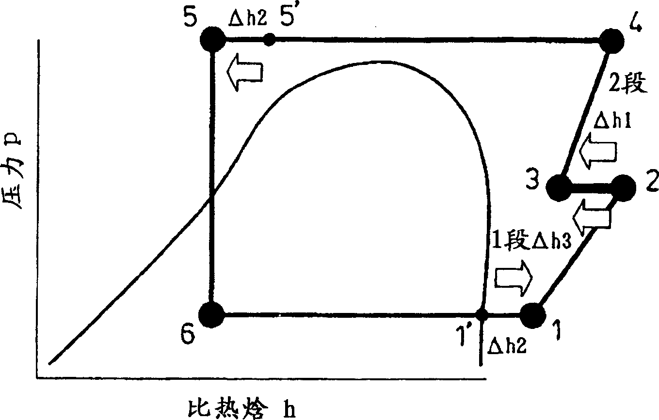
[0079] When using the following 2-stage compression conditions 1 and 2-stage compression conditions 2, and the lubricating oil recorded in Table 1 to carry out 2-stage compression, and other conditions are the same as in Example 1, in Table 3 and Figure 5 The results of the COP obtained during the test run are shown in .

[0080] (2-stage compression condition 1) The pressure on the high pressure side is 9MPa, and the pressure on the low pressure side is 3MPa.

[0081] (2-stage compression condition 2) The pressure on the high pressure side is 12 MPa, and the pressure on the low pressure side is 3.8 MPa.


PUM


Abstract

The present invention relates to a trans-critical refrigerating unit comprises a compressor 10, a gas cooler 154, a restriction means 156 and an evaporator 157 sequentially connected to each other, the trans-critical refrigerating unit using a refrigerant, which exhibits supercritical pressure on the high pressure side. In the unit, the compressor 10 includes compressing elements 32, 34 having a plurality of stages in a closed vessel 12, and after a discharge refrigerant in a lower-stage compressing element 32 in these compressing elements is discharged into the closed vessel 12 to dissipate heat, the refrigerant is further compressed by the subsequent-stage compressing element 34 to be discharged and a lubricating oil, which is compatible with said refrigerant and has a kinematic viscosity of 50 to 90 mm 2 / sec (@ 40 DEG C), is used. According to the trans-critical refrigerating unit of the present invention, the occurrence of sliding loss and leak loss is extremely suppressed and the maximum COP can be obtained.

Description

technical field [0001] The invention relates to a transcritical refrigeration device which is composed of a compressor, a gas cooler, a throttling mechanism and an evaporator connected in sequence, and the high pressure side is a supercritical pressure. Background technique [0002] Conventionally, Freons (R11, R12, R134a, etc.) have been generally used as refrigerants in refrigeration cycles. However, when CFCs are discharged into the atmosphere, there are problems such as the greenhouse effect and the destruction of the ozone layer. Therefore, in recent years, research on other natural refrigerants, such as oxygen (O 2 ), carbon dioxide (CO 2 ), hydrocarbons (HC), ammonia (NH 3 ), water (H 2 O). Among these natural refrigerants, oxygen and water are difficult to use as refrigerants of a refrigeration cycle due to their low pressure; ammonia and hydrocarbons have a problem of difficult handling due to their flammability. Therefore, people have developed a function tha...

Claims


Application Information

Patent Timeline
Patent Type & Authority Applications(China)
IPC IPC(8): F04B39/12C10M101/02C10M105/38C10M107/02C10M107/08C10M107/24C10M107/34C10N20/02C10N30/06C10N40/30F04C18/356F04C23/00F04C29/00F04C29/02F25B1/00F25B1/04F25B1/10F25B9/00F25B40/00
CPCF25B1/10F04C18/3564F04C23/001F25B2309/061F25B2500/16F25B9/008F25B1/00F25B9/00
Inventor 松本兼三藤原一昭高桥康树
Owner SANYO ELECTRIC CO LTD
Why Eureka
Try Eureka