Large mode field area large chromatic dispersion photonic crystal fiber

A photonic crystal fiber, large mode field technology, applied in the direction of light guide, optics, optical components, etc., to achieve the effect of large mode field area

Inactive Publication Date: 2005-09-21
TSINGHUA UNIV
View PDF0 Cites 9 Cited by
  • Summary
  • Abstract
  • Description
  • Claims
  • Application Information

AI Technical Summary

Problems solved by technology

This introduces a large nonlinear

Method used


Image

  • Large mode field area large chromatic dispersion photonic crystal fiber
  • Large mode field area large chromatic dispersion photonic crystal fiber
  • Large mode field area large chromatic dispersion photonic crystal fiber

Examples


Embodiment Construction

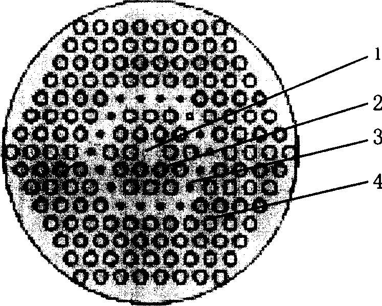
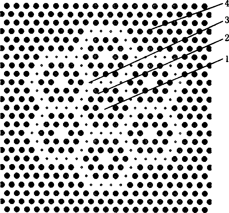
[0019] The large dispersion fiber includes seven groups of asymmetrically coupled double-core structures. Among them, six sets of double-core structures are evenly distributed along the circumferential direction. Another double-core structure is located in the center of the circumference. Each group is an asymmetrically coupled two-core structure. This asymmetrically coupled two-core structure can form a supermode. When the wavelength is changed, the distribution of supermodes in space will change. For example, when the wavelength is smaller than the phase matching wavelength of the inner core and the outer core, the mode field is distributed in the inner core; when it is in the phase matching wavelength of the inner core and the outer core, the mode field is distributed in the inner core and the outer core at the same time; When matching wavelengths, the mode field is mainly distributed in the outer core. The refractive index of the inner core and the outer core is differ...


PUM


Abstract

This invention relates to large field area and chromatic dispersion photon transistor in the field of fiber communication system chromatic dispersion compensation technique, which is characterized by the following: the fiber comprises non-symmetric couple double core structure with six groups evenly distributed along circle; the other group is located in the circle center, wherein, each group orderly comprises the following: inner core of solid silicon dioxide; inner cover layer composed of air holes and silicon dioxide along fiber radius direction; outer core of one ring of air hole with its radius of 40%+/-5%.

Description

technical field [0001] The invention belongs to the design and manufacture of photonic crystal fiber and the field of dispersion compensating device for optical fiber communication system. Background technique [0002] Dispersion compensation technology is the core key technology of high-speed optical fiber communication system. Dispersion compensating optical fiber is an important component of dispersion compensation in high-speed optical fiber communication system. Ordinary dispersion compensating fiber forms two asymmetric coupled cores by high doping in the core and low doping in the outer cladding. Near the phase matching wavelength, when the wavelength changes, due to the spatial redistribution of the mode field, the effective refractive index "felt" by different wavelengths is different, that is, when the wavelength changes, the group velocity changes, thus forming a large waveguide dispersion. Such dispersion compensating optical fibers generally form a core with ...

Claims


Application Information

Patent Timeline
Inventor 张冶金杨四刚谢世钟
Owner TSINGHUA UNIV
Why Eureka
Try Eureka