Prepn process of prefabricated rod for photon crystal fiber

A technology of photonic crystal fiber and preform, which is applied in glass manufacturing equipment, glass fiber products, manufacturing tools, etc., can solve problems such as interface loss and achieve the effect of overcoming the problem of interface scattering

Inactive Publication Date: 2005-09-28
SHANGHAI INST OF OPTICS & FINE MECHANICS CHINESE ACAD OF SCI
View PDF0 Cites 24 Cited by
  • Summary
  • Abstract
  • Description
  • Claims
  • Application Information

AI Technical Summary

Problems solved by technology

[0004] The purpose of the present invention is to solve the problem of interface loss caused by the stacking method for making photonic crystal optical fibers, and provide a method for preparing photonic crystal optical fiber preforms. The present invention is different from any previous technology for making photonic crystal optical fiber preforms

Method used


Image

  • Prepn process of prefabricated rod for photon crystal fiber
  • Prepn process of prefabricated rod for photon crystal fiber
  • Prepn process of prefabricated rod for photon crystal fiber

Examples


Embodiment Construction

[0035] In order to illustrate the present invention more clearly, the present invention will be further described below in conjunction with the examples and accompanying drawings, but the protection scope of the present invention should not be limited thereby.

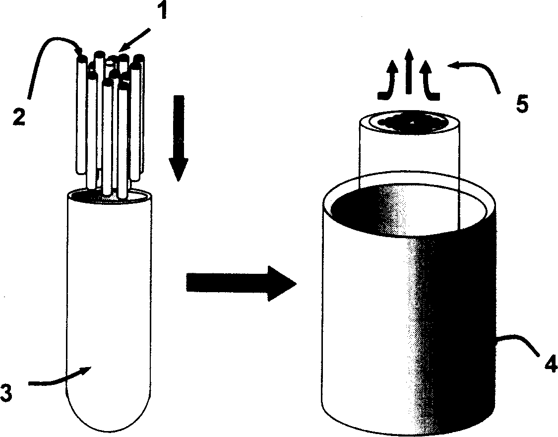
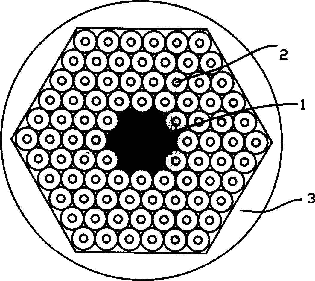
[0036] figure 1 Flow chart of making photonic crystal fiber preform for the present invention. The left part is a schematic diagram of filling the core-forming glass rod 1 and the capillary 2 into the jacket glass tube 3. The core-forming glass rod 1 and the capillary 2 are filled into the jacket glass tube 3 along the direction indicated by the vertical downward arrow. The right part is the process of placing the jacket glass tube 3 filled with the capillary 2 and the core-forming glass rod 1 in the heating furnace 4 for heating. Low air pressure inside the glass tube 3 tube. When the temperature of the heating furnace is kept higher than the softening point of the glass frit by 50°C to 200°C for about 120 minutes, ...


PUM


Abstract

The preparation process of prefabricated rod for photon crystal fiber includes the following steps: preparing capillary with sealed ends, outer glass pipe with one sealed end and glass core rod; setting the glass core rod inside outer glass pipe coaxially and arranging the capillaries orderly inside the outer glass pipe; setting the filled outer glass pipe inside fiber heating furnace with the opened end upwards; starting the vacuum pumping set and the heater to reach the required vacuum degree and temperature, moving the filled outer glass pipe downwards with the feeding mechanism for one period of homogeneous heating, and cooling to form the prefabricated rod for photon crystal fiber. The present invention has no interface scattering.

Description

technical field [0001] The invention relates to a photonic crystal fiber, in particular to a method for preparing a photonic crystal fiber prefabricated rod. Background technique [0002] Photonic crystal fiber is a hot spot in the field of fiber optic communication and fiber laser in recent years. Photonic crystal fiber is a two-dimensional photonic crystal, and its general structure is that air holes in the cross-section of the fiber are periodically distributed in the glass matrix material on the scale of light wavelength. Photonic crystal fiber structures are formed by introducing line defects into the periodic structure, such as changing the size of the aperture or replacing air holes with glass. The defect constitutes the core of the photonic crystal fiber, the periodic structure outside the defect constitutes the cladding, and the light propagates in the defect. Photonic crystal fibers are roughly divided into two types according to the difference in light guiding m...

Claims


Application Information

Patent Timeline
IPC IPC(8): C03B37/012
CPCC03B37/0122C03B37/0124C03B2203/04C03B2203/12C03B2203/14C03B2203/42
Inventor 杨旅云陈丹平达宁邱建荣姜雄伟朱从善
Owner SHANGHAI INST OF OPTICS & FINE MECHANICS CHINESE ACAD OF SCI
Why Eureka
Try Eureka