Vacuum adsorption equipment used for fixing thin-wall plane workpiece

A vacuum adsorption and plane technology, applied in positioning devices, metal processing machinery parts, clamping, etc., can solve the problems of sudden sealing of true suction holes, difficult workpiece cutting operation, and workpiece adsorption failure.

Inactive Publication Date: 2012-05-30
DALIAN INST OF CHEM PHYSICS CHINESE ACAD OF SCI
View PDF7 Cites 38 Cited by
  • Summary
  • Abstract
  • Description
  • Claims
  • Application Information

AI Technical Summary

Problems solved by technology

[0004] The invention provides a vacuum adsorption fastening device for clamping a thin-walled plane workpiece, which can solve the problem of sudden sealing of individual true suction holes during the working process of the vacuum adsorption fixture, which leads to the failure of workpiece adsorption and the difficulty in performing internal cutting operations on the workpiece. And other issues

Method used


Image

  • Vacuum adsorption equipment used for fixing thin-wall plane workpiece
  • Vacuum adsorption equipment used for fixing thin-wall plane workpiece
  • Vacuum adsorption equipment used for fixing thin-wall plane workpiece

Examples


Embodiment 1

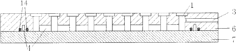
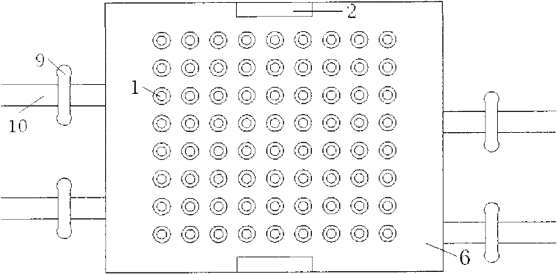
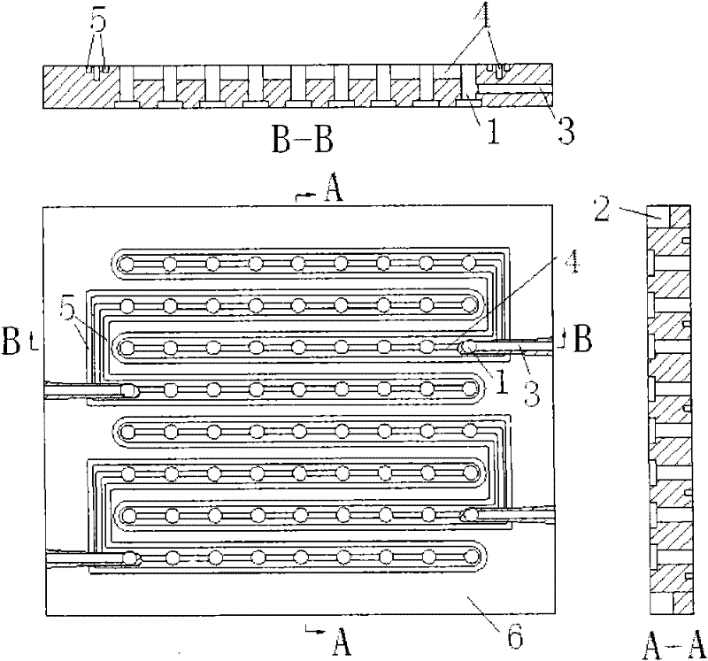
[0028] Such as figure 1 , 2 As shown in and 3, the utility model includes a vacuum adsorption plate 6 and a sealing cover plate 7, both of which are square plate-shaped structures, but are not limited to this shape. The surface of the vacuum adsorption plate is provided with a number of stepped suction holes that penetrate the vacuum adsorption plate, with a total of 8 rows and 9 columns. figure 2 In the middle position, number the rows ①~⑧ from top to bottom, and number the columns ①~⑨ from left to right. The lower surface of the vacuum adsorption plate is provided with 4 transverse "U"-shaped vacuum grooves which are not connected to each other. According to the position from top to bottom, the first groove and the second groove are nested with each other, and the lower "cross arm" of the first groove is located between the two "cross arms" of the second groove; The upper "cross arm" of the two grooves is located between the two "cross arms" of the first groove; the nest...

Embodiment 2

[0032] The vacuum adsorption device is the same as in Example 1.

[0033] Fasten with the suction device Figure 7 Workpiece 13 is shown. Before the workpiece 13 is processed, there is a radial square hole 11 that runs through the workpiece, and in the process of processing, it is necessary to cut out such as Figure 7The circular through hole 12 shown in. According to the size and position of the through holes, the suction holes in the ② and ③ rows in the ② row are located within the range of the hole 11, and the suction holes in the ⑤ row in the ④ row are located in the range of the hole 12 to be cut. Before the workpiece is processed, first use the suction hole plug 8 to block the corresponding suction hole to avoid the influence of the through hole 11 of the workpiece itself and the through hole 12 after processing on the vacuum adsorption, then place the workpiece 13, turn on the vacuum pump, and open All valves are switched on and off, and the machining process is per...


PUM


Abstract

The invention discloses vacuum adsorption equipment used for fixing a thin-wall plane workpiece, comprising a vacuum adsorption plate and a sealing cover plate. N suction holes penetrating through the vacuum adsorption plate are arranged on the upper surface of the vacuum adsorption plate, m vacuum grooves which are not communicated are arranged on the lower surface of the vacuum adsorption plate, and each vacuum groove is communicated with a plurality of suction holes and is also communicated with an air suction pipe of a vacuum-pumping system. Periphery of each vacuum groove is provided with surrounding vacuum grooves and annular sealing grooves which are not communicated, each vacuum groove is internally filled with a sealing material, and m vacuum adsorption regions which are not communicated are formed on the upper surface of the vacuum adsorption plate by the vacuum grooves and the sealing cover plate. By combining plugs of the suction holes, the problem that workpiece adsorption failure is caused by the fact that one suction hole is suddenly sealed in a working process of a vacuum adsorption device, the vacuum adsorption problem that a workpiece body is provided with a through hole and the problem of cutting operation inside a workpiece in the vacuum adsorption fixed mode can be solved.

Description

technical field [0001] The invention relates to a fastening device, in particular to a vacuum adsorption fastening device for clamping thin-walled plane workpieces. Background technique [0002] With the development of science and technology, the requirements for the manufacturing precision of product parts are getting higher and higher. For thin-walled workpieces, if the traditional peripheral clamping method is still used to fix them, it is very easy to deform under the joint action of fixture clamping force and tool cutting force during processing, which seriously affects the final dimensional accuracy of the workpiece. In order to solve this problem, vacuum adsorption can be used to fix thin-walled workpieces. The vacuum adsorption fixture is generally composed of two or more suction plates, upper and lower. There are suction holes on the upper suction plate that is in contact with the workpiece, and vacuum grooves with different structures are opened on the lower sucti...

Claims


Application Information

Patent Timeline
Patent Type & Authority Applications(China)
IPC IPC(8): B23Q3/06
Inventor 张华民马海鹏刘波
Owner DALIAN INST OF CHEM PHYSICS CHINESE ACAD OF SCI
Why Eureka
Try Eureka