Air-pressure water raiser

A technology of air-compressed water pump and water-pressed water pump, which is applied in the direction of pressure pump, mechanical equipment, machine/engine, etc., can solve problems such as the failure of floaters, and achieve the effect of effective control

Inactive Publication Date: 2005-09-28
张传松
View PDF1 Cites 11 Cited by
  • Summary
  • Abstract
  • Description
  • Claims
  • Application Information

AI Technical Summary

Problems solved by technology

However, in this air-compressed water lifter, when the intake air pressure is too large or the water level changes, and the flow rate of the water inlet is smaller than the water volume ...

Method used


Image

  • Air-pressure water raiser

Examples


Embodiment Construction

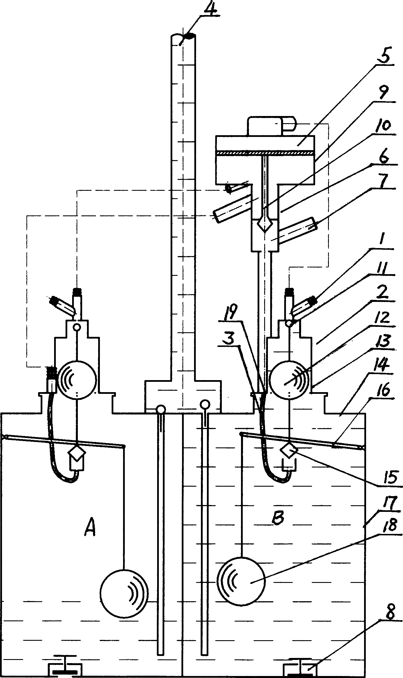
[0010] Such as figure 1 Shown, the present invention comprises two by the casing 17 that has water inlet 8, water outlet 4 and air intake, exhaust control mechanism and control exhaust mechanism, and water inlet 8 is positioned at casing 17 bottoms, and other each mouth is positioned at casing. On the upper cover plate 14 of the body 17. Above the air inlet 19 of one of the casings, there is an air inlet valve 6. The valve body 9 of the valve includes two cavities up and down, and its lower chamber is connected with the air inlet of the casing B and the total air inlet pipe 7. The upper cavity is connected with the intake pipe 3 of the casing A. The valve plug on the valve stem 10 of the intake valve 6 is located in the lower cavity of the valve body 9, and it is controlled by the cylinder 5 above it. The upper cavity of the cylinder 5 is connected with the exhaust port of the casing B through the air guide pipe with the exhaust pipe, and its lower cavity is connected with t...


PUM


Abstract

The present invention relates to air pressure water raiser, and aims at providing an air pressure water raiser with simple structure, low cost and effective control. The air pressure water raiser includes two boxes with water inlet, water outlet, air inlet, air outlet and air intake and exhaust controlling mechanism, and air intake pipe and air intake valve set in at least one of the air inlets. The air intake valve is connected to the exhaust controlling mechanism.

Description

technical field [0001] The invention relates to an air pressure water lifter utilizing wind energy as power, in particular to an air pressure water lifter with automatic air intake control. Background technique [0002] No. 00256343.6 Chinese patent in the prior art discloses a kind of air pressure pumping machine, and it comprises two and passes through the box body that has inlet, outlet and air intake, exhaust control mechanism and control exhaust mechanism, said air intake , The exhaust control mechanism includes a cylinder, the two cavities of the cylinder piston are respectively connected to the exhaust ports with float valves on each box through the air pipes with exhaust ports, and the piston rod of the cylinder is connected to the intake valve. Valve rod, its valve body has two chambers: the upper chamber is connected with the intake pipe of another box body, the lower chamber is connected with the air inlet of this side box body and the total intake pipe, and the p...

Claims


Application Information

Patent Timeline
IPC IPC(8): F04F1/06
Inventor 张延胜张传松
Owner 张传松
Why Eureka
Try Eureka