Improved fuel delivery system

A technology of fuel delivery and fuel, which is applied in the direction of turbine/propulsion fuel delivery system, charging system, fuel valve of turbine/propulsion device, etc. It can solve the problems of reducing components, increasing the number of components, etc., and achieving the effect of improving capacity

Inactive Publication Date: 2005-09-28
ARGO TECH CORP
View PDF0 Cites 22 Cited by
  • Summary
  • Abstract
  • Description
  • Claims
  • Application Information

AI Technical Summary

Problems solved by technology

While other systems in the prior art have used bypassing as an attempted solution, the adoption of this approach increases the number of components, contradicting the trend to reduce components

Method used


Image

  • Improved fuel delivery system
  • Improved fuel delivery system
  • Improved fuel delivery system

Examples


Embodiment Construction

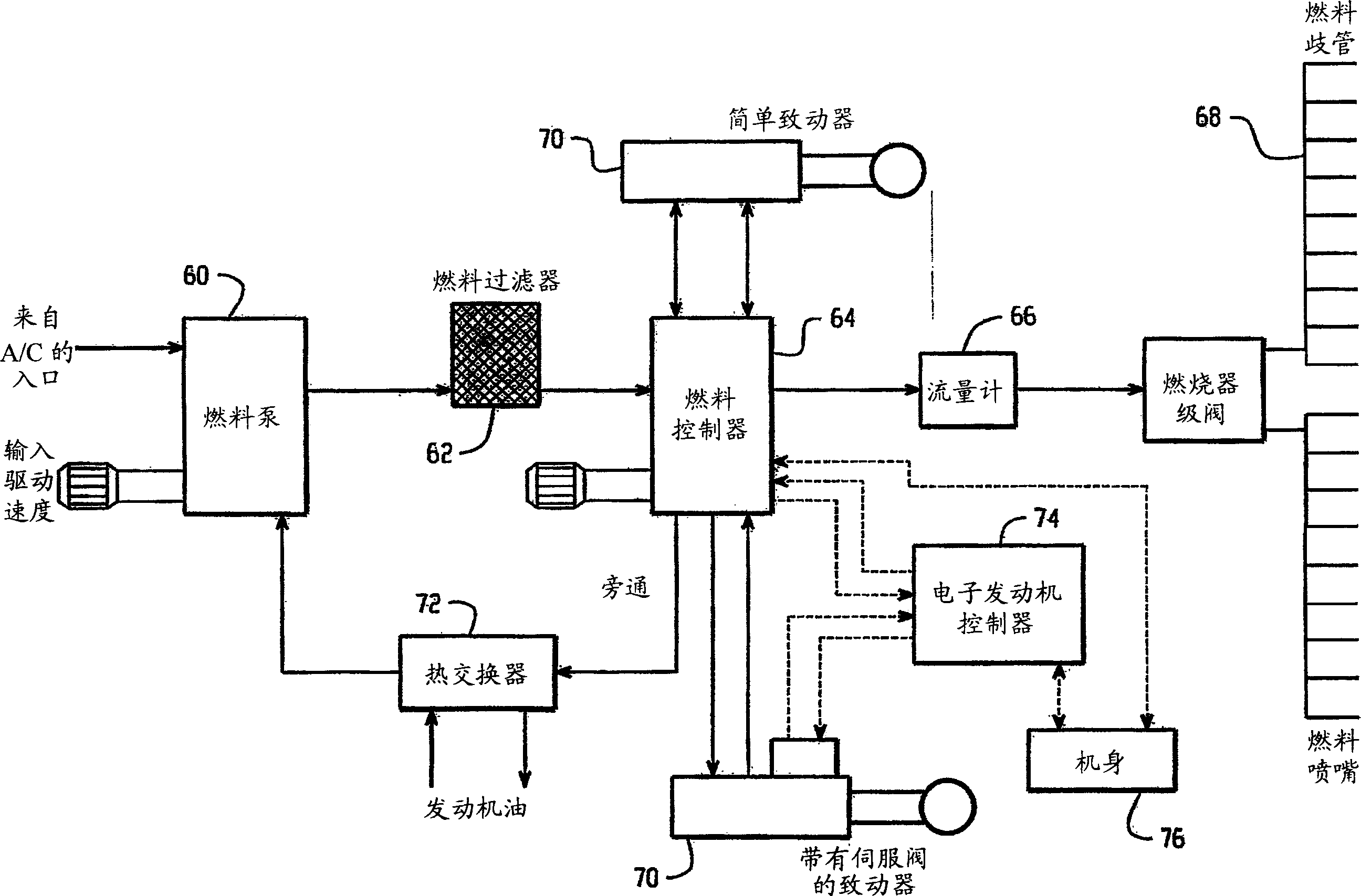
[0023] By way of additional background to the present invention, Figure 1 schematically shows a high level and more detailed conventional engine fuel system. As such systems are generally known to those skilled in the art, only a brief summary of selected portions is provided to understand the features and benefits provided by the present invention.

[0024] As shown schematically in the high-level view in FIG. 1 , the prior art system includes a fuel pump 60 for supplying fuel to a fuel controller 64 through a filter 62 . The pump is a displacement device that delivers a quantitative flow of fuel to the fuel controller based on engine speed. The delivered portion of the fuel flow is metered and delivered to an engine combustion chamber (not shown). The metered portion of the fuel flow is supplied to the combustion chamber by fuel flow meter 66 before reaching the fuel distribution manifold and fuel nozzles 68 . Another portion of the fuel flow delivered by the pump goes to ...


PUM


Abstract

A fuel delivery system provides for closed loop mass flow control of fuel between a metering valve and a pump, such as a variable delivery pump. Changes in pressure across the metering valve are monitored and pump operation is altered in response thereto. A thermal controller monitors fuel temperature and recirculates a portion of the fuel flow through a heat exchanger. The fuel delivery system can be provided as original equipment or as a retrofit.

Description

technical field [0001] The present invention relates to turbine engine assemblies and, more particularly, to fuel delivery systems for such engines. It should be appreciated, however, that the system may be found equally applicable in related systems or environments requiring high reliability, low cost, and low weight without sacrificing performance. Background technique [0002] Current common fuel delivery systems typically use a centrifugal boost stage to introduce pressurized fluid into a filter and then pass the pressurized fluid through a gear stage or gear pump. The fuel then flows to the metering valve, into the pressure control valve, from which the fuel eventually flows to the fuel nozzles associated with the turbine engine. With changing pump suction conditions, the centrifugal propulsion stage provides pressure and fuel flow to adequately fill the high pressure stage with a uniform liquid fuel (ie, no vapor). For example, pump suction conditions may include low...

Claims


Application Information

Patent Timeline
Patent Type & Authority Applications(China)
IPC IPC(8): F02C7/232F02C9/26F02C9/28F02C9/30F04C2/18F04C2/344F04C14/22
CPCF05D2270/303F04C2270/20F04C2/18F04C2270/19F04C2/3442F02C9/263F02C9/30F04C14/226F02C9/26
Inventor 马丁·A·克莱门茨
Owner ARGO TECH CORP
Why Eureka
Try Eureka