
Method for extracting oil and gas by convection heating of oil shale

A convective heating and oil shale technology, applied in the fields of fluid production, earthwork drilling, wellbore/well components, etc., can solve problems such as high cost, low efficiency, heat loss, etc., and achieve improved oil and gas recovery and low cost. , the effect of uniform temperature rise

Active Publication Date: 2005-10-05
TAIYUAN UNIV OF TECH
View PDF12 Cites 92 Cited by
  • Summary
  • Abstract
  • Description
  • Claims
  • Application Information

AI Technical Summary

Problems solved by technology

[0006] The above-mentioned methods for underground in-situ exploitation of oil and gas in oil shale all have disadvantages such as high cost, low efficiency, small scale and serious heat loss.

Method used


Image

  • Method for extracting oil and gas by convection heating of oil shale
  • Method for extracting oil and gas by convection heating of oil shale
  • Method for extracting oil and gas by convection heating of oil shale

Examples


Embodiment 1

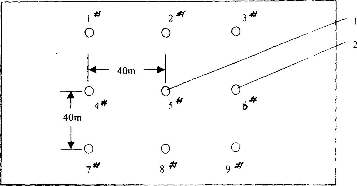
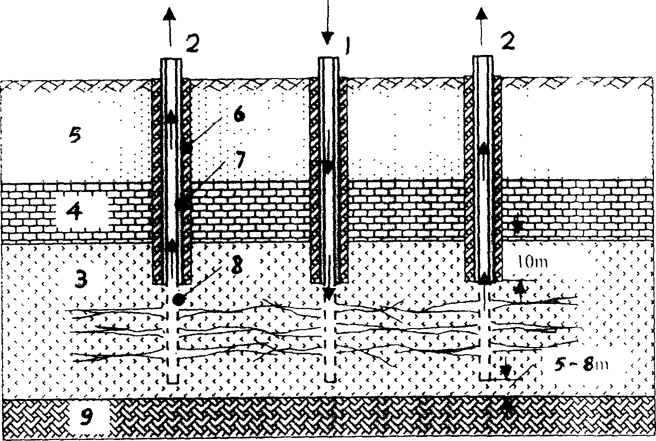
[0035] Such as figure 1 , 2 As shown, a method for convection heating oil shale to extract oil and gas, in a single oil shale layer with a thickness of 30m and a buried depth of 100m, 9 wells are arranged by the present invention, with a well spacing of 40m and a square shape Grid distribution, each well is located at the intersection of the square grid, each well is drilled into the ore layer 3, and then lowered into the double-layer annular pipe 7, the double-layer annular pipe 7 is made of high-temperature-resistant seamless steel pipe with an inner diameter of 150mm, and The top of floral tube 8 is connected, and the length of floral tube is 15m, and it is 5~8m apart from bottom plate 9 when going down into ore layer, and leaves about 10m apart from ore layer top plate 4. The flower tube and the double-layer annular pipe are still in the elastic state of the material under the continuous action of the high temperature of 700°C and the horizontal thermal expansion stress 2...

Embodiment 2

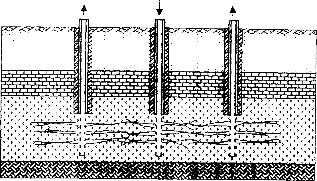
[0045] Such as Figure 4 , 5 As shown, a method for convectively heating oil shale to exploit oil and gas, a certain oil shale layer group contains three layers of oil shale layer 3, the thickness of the oil shale layer from bottom to top is 10m, 25m, 8m respectively, and the interlayer is The thickness of sandstone is 3m and 4m respectively. The accumulative thickness of this ore layer group is 43m, and the ore-bearing coefficient is 86%. The wells are arranged in equilateral triangle with the spacing of 50m and 11 wells are arranged.

[0046] Drill wells with the method of embodiment 1, each well is drilled into the ore layer 3, and then lowered into the double-layer annular pipe 7, the inner diameter of the double-layer annular pipe is 150mm, connected with the top of the flower pipe 8, the length of the flower pipe is 15m, and lowered into The ore seam is 5-8m away from the bottom plate 9, and 5-10m is reserved from the ore seam roof 4.

[0047] Specific steps are as fol...


PUM


Abstract

A kind of mining oil gas method of the convection heating up oil-shale, involves the underground solid state energy and the mineral mining method improvement. The existing technical mining method efficiency is low, the cost is high, the scale is small, the big area implements and lacks the market competition ability with difficulty. This invention through in the ground arrangement group well, and selects the compression fracture method causes the group well to be interlinked, then the gap takes turns to choose the note hot-well and work-well, hot-well pours into 400 deg.C - 700 deg.C steam along the note oil-shale the ore level, heats up the ore level causes cheese root thermal decomposition to form the oil gas, and carries after the low temperature steam or the water along the production separates to the ground, finally forms the oil gas product. In the separation process may simultaneously the pre- hot water, and uses the water-injection well withdraws with work-well the convection way dries up oil-shale and the ore level around shale region afterheat, thus realized the goal of this invention is fast, big scale, low cost from oil-shale ore level mining oil gas.

Description

technical field [0001] The invention relates to a method for producing oil and gas from an underground oil shale layer (containing kerogen), more specifically, relates to a method of utilizing group wells for fracturing, using superheated high-temperature pressure steam to heat the oil shale layer in a convective manner, so that A method for exploiting oil and gas by pyrolysis of kerogen. Background technique [0002] China has extremely rich oil shale resources. So far, only a very small amount of oil shale has been exploited through open-pit raw ore mining, and then the oil and gas are obtained through dry distillation in chemical plants; For power generation and combustion. In recent years, the Chinese invention patents related to the method and device for producing oil and gas by dry distillation on the ground include: "The dry distillation method of oil shale and all its devices" (CN1013501B) issued by the Industrial Technology Research Institute of Japan, "The dry dis...

Claims


Application Information

Patent Timeline
Patent Type & Authority Applications(China)
IPC IPC(8): E21B43/241E21B43/30
Inventor 赵阳升冯增朝杨栋刘生玉孙可明赵建忠关克伟段康廉
Owner TAIYUAN UNIV OF TECH
Learn More