
Purifying system and method

A technology for accommodating tubes and covering bodies, applied in the field of purification systems, can solve the problems of deterioration, low yield of purified products, inability to reduce costs and purification procedures and time, and achieve the effect of reducing wear and tear

Active Publication Date: 2005-10-19
泰世康有限公司
View PDF0 Cites 4 Cited by
  • Summary
  • Abstract
  • Description
  • Claims
  • Application Information

AI Technical Summary

Problems solved by technology

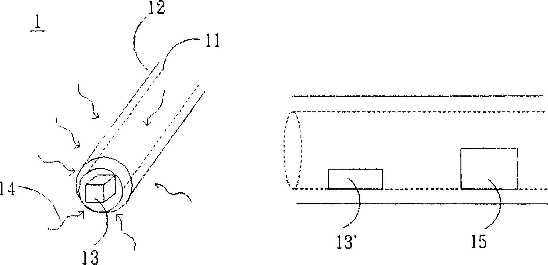
like figure 1 As shown, as the amount of the substance to be purified 13 is more, after applying heat energy 14 to the cladding body 12, due to the relationship between the diameter and distance between the housing tube 11 and the cladding body 12, the central point of the housing tube 11 and the The tube wall will have a temperature difference, so that the temperature uniformity of the whole object to be purified 13 is insufficient and deteriorated, so after the sublimation is completed, there are often still many remaining objects to be purified 13 ' that have not been sublimated, and some objects to be purified 13 have been due to The temperature is too high to produce cracking, that is, as figure 1 As shown, the resulting purified product 15 was not ideal in yield
On the other hand, since the purification system 1 only includes one holding tube 11, it can only be used to purify one type of organic substance in one heat sublimation process, which is quite uneconomical and time-consuming.
[0004] Based on the above, in order to develop various materials to promote the application of light-emitting diodes and displays, the existing purification systems generally have insufficient temperature uniformity, low yields of purified products, and cracking losses of the purified products during the purification process. Disadvantages that cost and purification procedures and time cannot be reduced

Method used


Image

  • Purifying system and method
  • Purifying system and method
  • Purifying system and method

Examples


Embodiment Construction

[0015] The purification system and purification method according to preferred embodiments of the present invention will be described below with reference to the relevant drawings, wherein the same components will be described with the same reference numerals.

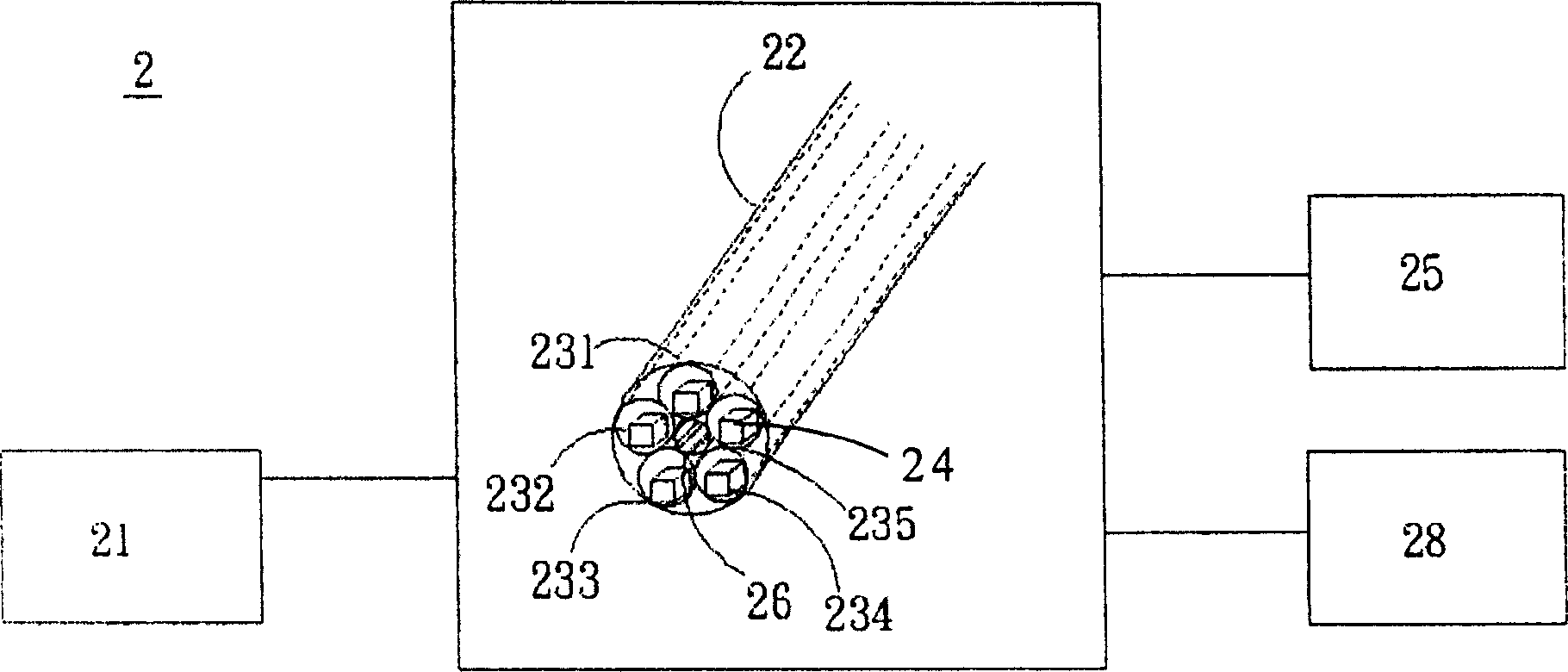
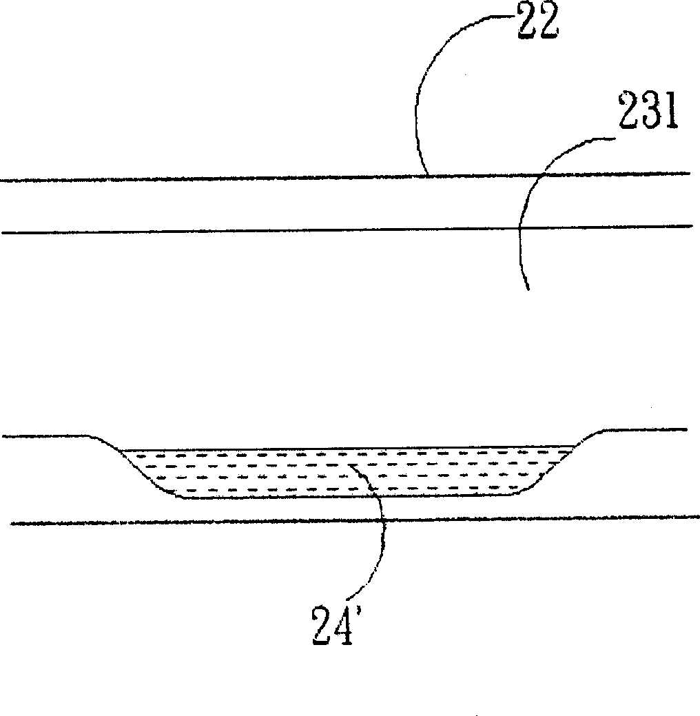
[0016] see figure 2 , which is a schematic diagram of a purification system according to a preferred embodiment of the present invention. In this embodiment, the purification system 2 includes an input device 21 , a cladding body 22 , containing tubes 231 to 235 , a high temperature furnace 25 , a heater 26 and an output device 28 . Wherein, the input device 21 is used to input at least one object to be purified 24 to at least any one of the holding tubes 231 to 235, and each object to be purified 24 can be solid and liquid organic materials with different sublimation points to be purified. , or more than one other substances to be purified with similar sublimation points can be input into the holding tubes 231 to 235...


PUM


Abstract

The present invention relates to a kind of purifying system and method. The purifying system includes several holding pipes and one covering body to cover the holding pipes, and the holding pipes are used to hold at least one kind of matter to be purified. The present invention can reduce the loss of the purified matter in the purifying process and obtain purified matter with high yield.

Description

technical field [0001] The invention relates to a purification system and method, in particular to a purification system and method which utilizes a plurality of holding tubes to improve material temperature uniformity and yield. Background technique [0002] As the technology of flat-panel display products gradually develops toward high-quality, light weight, large-scale, and low-cost trends, various material technologies have become key technologies for flat-panel displays to meet the above requirements, such as high-color-gamut materials, high-response-speed liquid crystal materials, Development of high brightness materials, wide viewing angle materials and non-brush mode materials for large areas. Among them, compared with other flat-panel display technologies, organic light-emitting diode displays (OLEDs) have advantages such as self-illumination, high brightness, wide viewing angle, high contrast, low power consumption, high-speed response, wide operating temperature r...

Claims


Application Information

Patent Timeline
IPC IPC(8): B01D7/00
Inventor 林政弘游振萍柯崇文
Owner 泰世康有限公司
Learn More