
Ion implanting apparatus

An ion implantation device and ion beam technology, which are used in measurement devices, instruments, and material analysis by optical means, etc., can solve the problems of reduced substrate processing speed, deterioration of uniformity, and large inhomogeneity of beam current density distribution. , to achieve the effect of suppressing the decrease in uniformity and the deterioration of parallelism, and improving the uniformity

Inactive Publication Date: 2005-11-23
NISSIN ION EQUIP CO LTD
View PDF1 Cites 25 Cited by
  • Summary
  • Abstract
  • Description
  • Claims
  • Application Information

AI Technical Summary

Problems solved by technology

That is, the uniformity of the beam current density distribution in the ion beam width direction deteriorates
[0004] In the said special form No. 2000-505234 bulletin (page 14, line 14-page 15, line 15, figure 1 In the ion implantation apparatus described in ), although it can be considered that the non-uniformity of the beam current density distribution caused by the above-mentioned reasons is corrected by using the multipole ion lens provided on the upstream side of the mass separation magnet by using the local deflection of the ion (for example, the ion beam Bending toward the area with low current density to increase the current density in this area), but the unevenness of the beam current density distribution caused by the above reasons is very large, and there is a limit to correcting it with a multipolar ion lens
[0005] In addition, when the ion beam is largely deflected by the multipole ion lens to correct the non-uniformity of the beam current density distribution, the deflection causes another problem that the parallelism in the width direction of the ion beam deteriorates.
[0006] Such a problem will become more serious when the width of the ion beam guided from the mass separation magnet is increased corresponding to the enlargement of the substrate (for example, a substrate with a short side width of about 600 mm or more).
[0007] In addition, in the above-mentioned prior art that utilizes the divergence of the ion beam extracted from the ion source to widen the width of the ion beam, since the beam current density becomes lower as the width of the ion beam becomes wider, when corresponding to an increase in the size of the substrate, The processing speed per substrate is reduced

Method used


Image

  • Ion implanting apparatus
  • Ion implanting apparatus
  • Ion implanting apparatus

Examples


Embodiment Construction

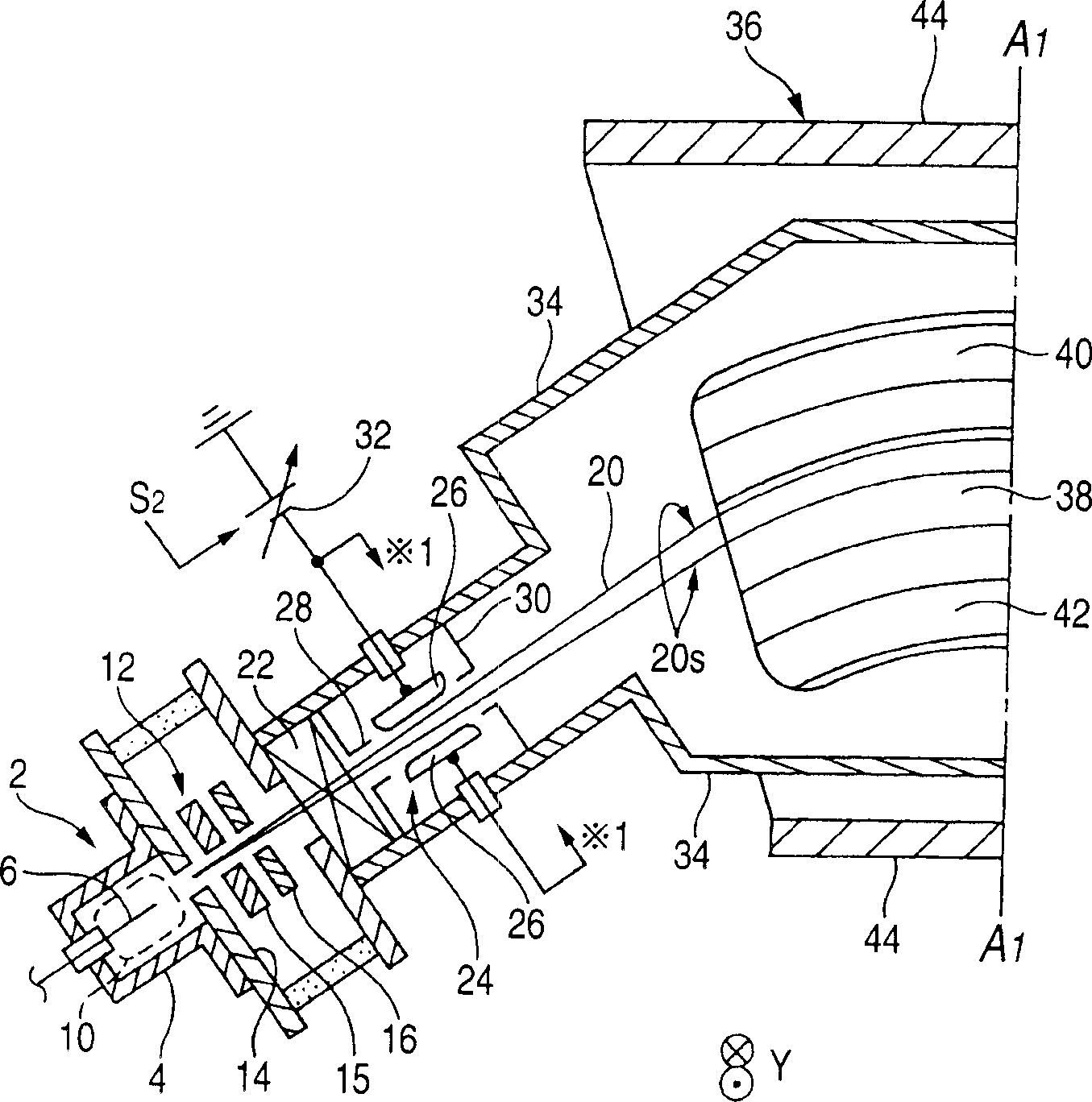
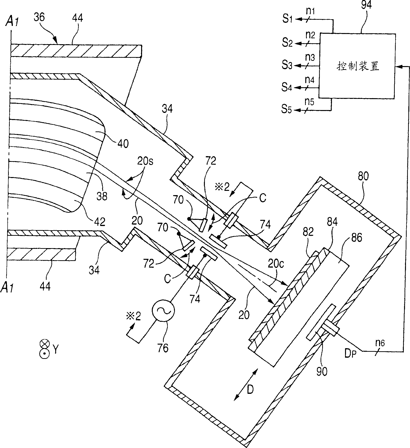
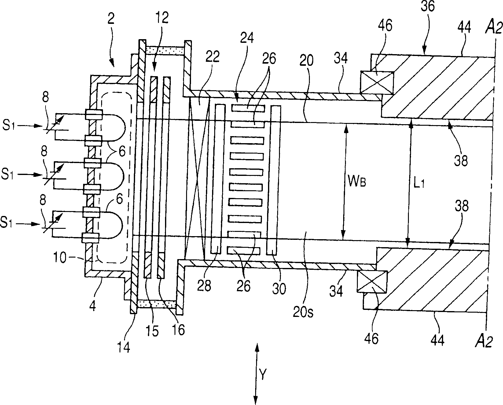
[0049] figure 1 It is a cross-sectional view showing a part of the ion implantation apparatus of the present invention, and the part of the line A1-A1 and figure 2 connect. figure 2 is a cross-sectional view showing the remaining part of the ion implantation apparatus of the present invention, the part of the line A1-A1 and figure 1 connect. image 3 yes means figure 1 and figure 2 A longitudinal sectional view of a part of the ion implantation apparatus shown, the part of the line A2-A2 is connected with Figure 4 connect. Figure 4 yes means figure 1 and figure 2 A longitudinal sectional view of the remaining part of the ion implantation apparatus shown, the part of the line A2-A2 is connected with image 3 connect.

[0050] In principle, the ion implantation device will, for example, Figure 6 A rectangular substrate 82 is shown as an object to be processed. The width of the short side 82a of the substrate 82 is referred to as the short side width WS. Howeve...


PUM


Abstract

The ion implanting apparatus according to this invention includes: an ion source for producing the ion beam 20 including desired ion species and being shaped in a sheet with a width longer than a narrow width of a substrate 82, a mass separating magnet 36 for selectively deriving the desired ion species by bending the ion beam in a direction perpendicular to a sheet face thereof, a separating slit 72 for selectively making the desired ion species pass through by cooperating with the mass separating magnet 36, and a substrate drive device 86 for reciprocatedly driving the substrate 82 in a direction substantially perpendicular to the sheet face 20 s of the ion beam 20 within an irradiating area of the ion beam 20 which has passed through a separating slit 72.

Description

technical field [0001] The present invention relates to, for example, an ion implantation device for irradiating an ion beam on a substrate such as a semiconductor substrate or a substrate for a flat panel display (in other words, a processed object or an object to be processed, the same applies hereinafter), and more specifically relates to An ion implantation apparatus that can well cope with an increase in the size of a substrate (in other words, increase in area; the same applies hereinafter). In addition, a device called ion doping is also included in the ion implantation device referred to here. Background technique [0002] In Special Form No. 2000-505234 (line 14 on page 14 - line 15 on page 15, figure 1 ) describes an example of an ion implantation apparatus capable of irradiating a wide width and parallelized ion beam onto a substrate. This ion implanter has a structure in which a fan-shaped ion beam diverging in one direction is extracted from a small ion source...

Claims


Application Information

Patent Timeline
Patent Type & Authority Applications(China)
IPC IPC(8): H01J37/317G01N21/00H01L21/265
CPCH01J2237/057H01J2237/24542H01L21/26513H01J2237/24528H01J2237/1502H01J37/3171H01J2237/20228H01J2237/0455H01L21/2658H01L21/265
Inventor 前野修一内藤胜男安东靖典希尔顿·F·格拉维什
Owner NISSIN ION EQUIP CO LTD
Learn More