Electric discharge machine and machining fluid cooling device

A technology of electric discharge machine and cooling device, which is applied in the direction of electric processing equipment, metal processing equipment, electrode manufacturing, etc., can solve the problems of poor machining accuracy and no consideration of temperature fluctuation of working fluid, etc., and achieve the effect of improving machining accuracy

Inactive Publication Date: 2005-11-30
FANUC LTD
View PDF1 Cites 7 Cited by
  • Summary
  • Abstract
  • Description
  • Claims
  • Application Information

AI Technical Summary

Problems solved by technology

[0014] Therefore, finishing is performed at the position of the wire electrode route during rough machining, and there is a gap between the rough machining route and the finishing route, leading to poor machining accuracy
[0015] As mentioned above, although the temperature of the traditional working fluid is controlled, this temperature control is carried out in the clean liquid tank on the inlet side of the working fluid discharge pump, and the working fluid discharged on the discharge side of the working fluid discharge pump There is no temperature control on the pump, so the temperature fluctuation of the working fluid caused by the working fluid discharge pump itself is not considered

Method used


Image

  • Electric discharge machine and machining fluid cooling device
  • Electric discharge machine and machining fluid cooling device
  • Electric discharge machine and machining fluid cooling device

Examples


Embodiment Construction

[0038] A detailed description will now be given of preferred embodiments of the present invention with reference to the accompanying drawings.

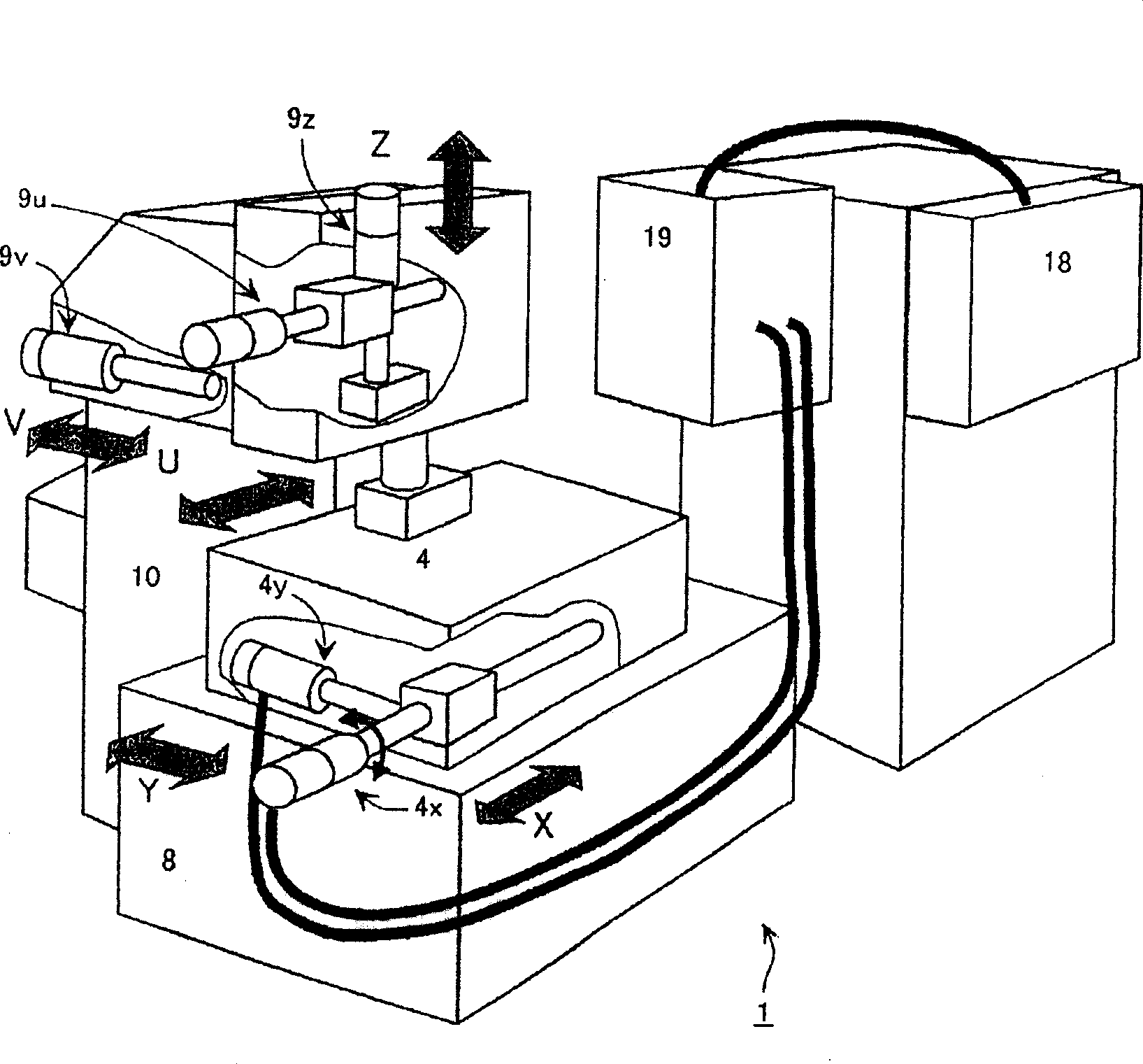
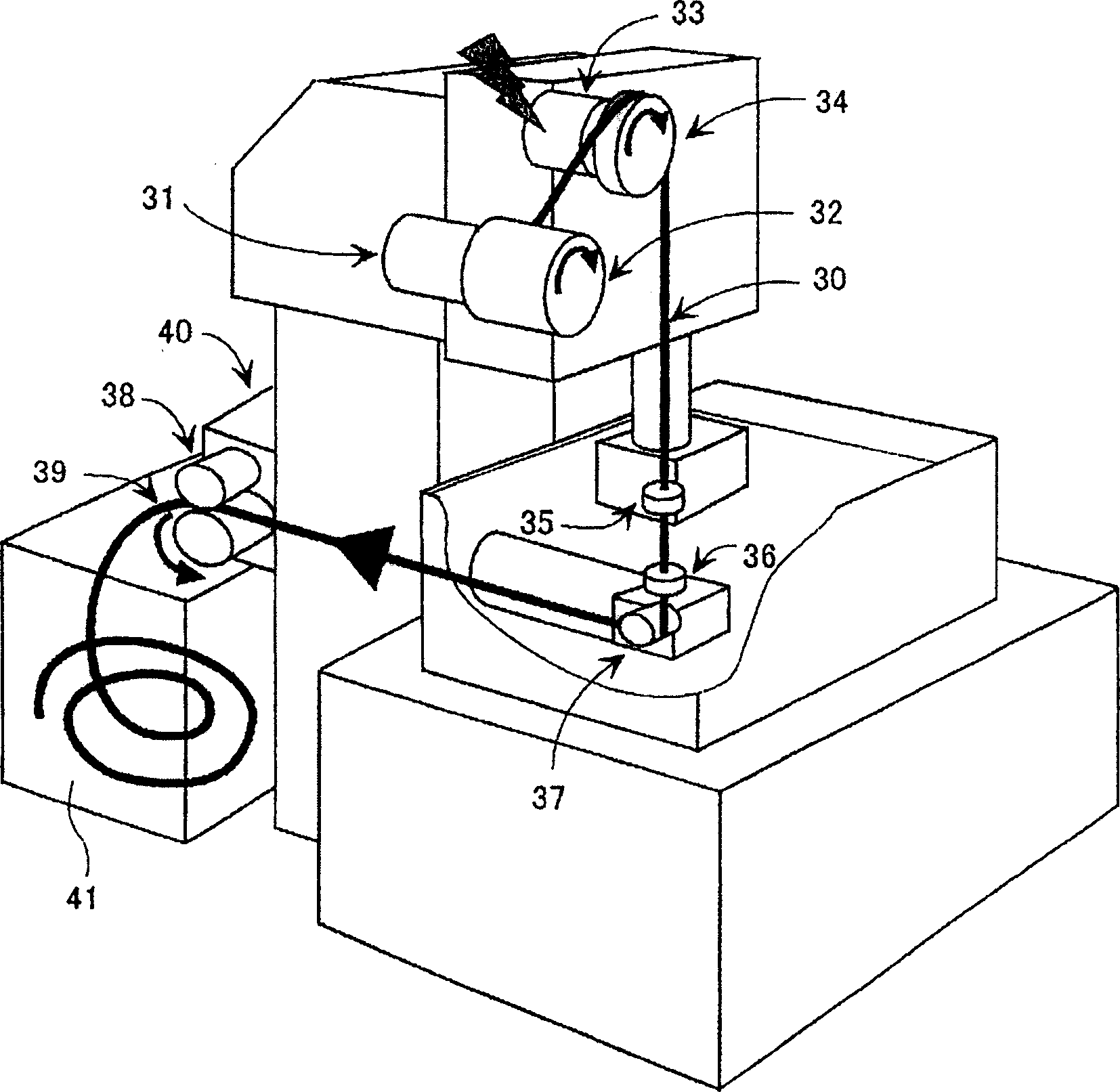
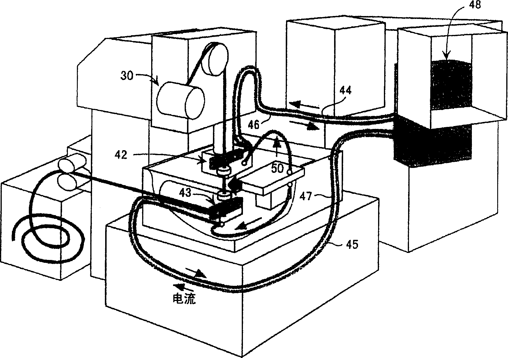
[0039] Figure 1-4 Schematically shows the structure of a discharge and add electrical machine. figure 1 The mechanical structure of the electrical discharge machine is schematically shown. figure 2 A routing system for wire electrodes is schematically shown; image 3 Schematically showing the flow of electric discharge machining current; Figure 4 The flow of the working fluid is schematically shown.

[0040] exist figure 1 Among them, an electrical discharge machine 1 includes a table 4 on which a workpiece is mounted, and a support 10 supporting an upper end guide for guiding a wire electrode. The table 4 is movable in the X and Y axis directions on top of a machine tool 8, and is provided with a driving mechanism 4x and a driving mechanism 4y. The drive mechanism 4x includes a motor and a ball screw for movement in the X di...


PUM


Abstract

An electric discharge machine controls temperature fluctuations of machining fluid discharged by a discharge pump so as to improve machining accuracy, and a machining fluid cooling device keeps the temperature of the discharged machining fluid constant regardless of the operating state of the discharge pump. The electric discharge machine pumps machining fluid in a temperature controlled clean fluid tank with a discharge pump and discharges the machining fluid to a machining area through piping, and has a machining fluid cooling device for cooling machining fluid discharged from the discharge pump. The machining fluid cooling device passes a portion of the piping through the clean fluid tank and exchanges heat between the machining fluid inside the piping and the clean fluid in the clean fluid tank, thus dispersing the heat added from the discharge pump to the clean fluid side and lowering the temperature of the machining fluid inside the piping.

Description

technical field [0001] The present invention relates to an electrical discharge machine in which working fluid is supplied to an electrical discharge machining zone, and particularly to a working fluid cooling device for cooling the working fluid, and an electrical discharge machining device provided with the working fluid cooling device machine. Background technique [0002] In a wire-cut electrical discharge machine, a workpiece is machined by spark discharge between the workpiece and a wire electrode. Working fluid is supplied by a pump to the workpiece and the wire electrode, thereby removing debris while cooling the EDM zone to prevent temperature rise. [0003] The faster the processing speed, the greater the pressure at which the working fluid is supplied to the processing zone. As a result, the faster the entrapped slag is removed from the processing zone. Furthermore, the cooling effect on the wire (the temperature of the wire increases due to the electric discha...

Claims


Application Information

Patent Timeline
Patent Type & Authority Applications(China)
IPC IPC(8): B23H1/10B23H7/10B23H7/36
CPCB23H7/101B23H7/36B23H1/10
Inventor 荒川靖雄山口巡
Owner FANUC LTD
Why Eureka
Try Eureka