Method for making electric control zooming and optical imaging system

A technology of an optical imaging system and a manufacturing method, which is applied in the field of electronically controlled zoom optical imaging systems, can solve problems such as unfavorable system integration and miniaturization, slow zoom speed, and bulky volume, and achieve quantity saving, short response time, and ease of use. integrated effect

Inactive Publication Date: 2005-11-30
UNIV OF SHANGHAI FOR SCI & TECH
View PDF0 Cites 12 Cited by
  • Summary
  • Abstract
  • Description
  • Claims
  • Application Information

AI Technical Summary

Problems solved by technology

There are mechanical moving parts in the traditional optical imaging zoom system, the zoom speed is slow, the energy consumption is large, and the volume is bulky, which is not conducive to the integration and miniaturization of the system

Method used


Image

  • Method for making electric control zooming and optical imaging system
  • Method for making electric control zooming and optical imaging system
  • Method for making electric control zooming and optical imaging system

Examples


Embodiment Construction

[0018] The present invention will be further described below in conjunction with the embodiments and the accompanying drawings.

[0019] Implementation steps of the present invention are:

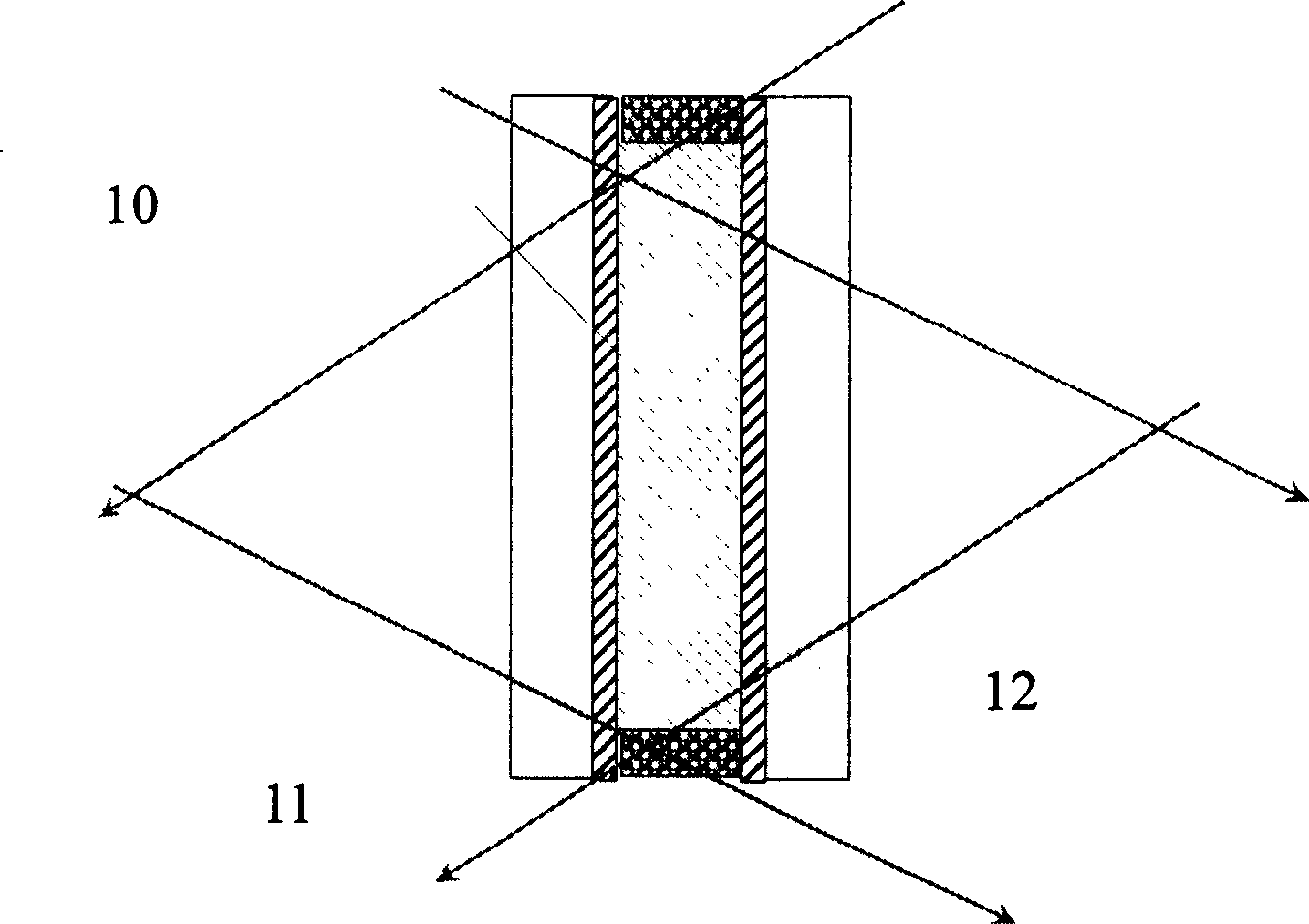
[0020] 1. Preparation of liquid crystal grating element: it includes two glass substrates coated with a conductive layer, and a recording layer composed of 5-10μ PDLC material is filled in the glass substrate;

[0021] 2. Design the holographic optical path with the laser holographic method, and make a holographic lens on the recording layer. The lens effect can be erased under the action of an AC electric field of 5-50V;

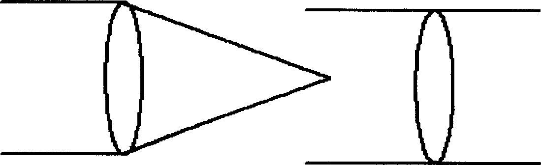
[0022] 3. Design different holographic optical paths, and use the same method to make holographic diffraction lenses with different focal lengths;

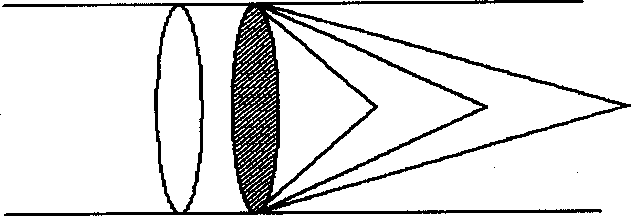
[0023] 4. Superimpose, combine and integrate a group of lenses with different focal lengths into an optical imaging system;

[0024] 5. The computer program calculates and controls the electric field of a single zoom lens ...


PUM


Abstract

This invention discloses a method for producing electric controlling variable-focus optical imaging system, which comprises the following steps: a) preparing two pieces of glass chip with nesa, b) coating a recording layer mixed of the pre-polymeric material of photo-induced solidifying high polymer with length of 5-10mu m and liquid crystal between the glass chip, c) designing the different holographic optical path to prepare electric controlling focusing holographic lens with different focus by laser holography or computer holography, d) superimposing N electric control lenses with different focus parameter, e) adjusting the electrical field controlling order, then getting 2N focuses, f) computing and controlling field controlling combination and order of single lens to achieve the function of continuous magnification of optical system.

Description

technical field [0001] The invention relates to a manufacturing method of an optical imaging system, in particular to a manufacturing method of an optical imaging system whose optical imaging focal length is continuously adjustable under the action of an electric field. Background technique [0002] The zoom optical imaging system produced by traditional methods, such as point-and-shoot cameras, generally uses a small motor to adjust the distance between the lens groups to achieve the system focus function; zoom glasses. The traditional optical imaging zoom system has mechanical moving parts, slow zoom speed, high energy consumption, and bulky volume, which is not conducive to system integration and miniaturization. Contents of the invention [0003] The present invention aims to provide a non-mechanical, low power consumption, fast speed, favorable system miniaturization and integration, and a manufacturing method of an optical...

Claims


Application Information

Patent Timeline
Patent Type & Authority Applications(China)
IPC IPC(8): G02B7/04
Inventor 郑继红庄松林顾玲娟苏锦文
Owner UNIV OF SHANGHAI FOR SCI & TECH
Why Eureka
Try Eureka