Ultrasonic wave wire soldering method and wire soldering apparatus

A welding wire device, ultrasonic technology, applied in welding equipment, non-electric welding equipment, electrical components, etc., can solve the problems of wasting time, welding wire speed limitation, unable to monitor and improve welding wire quality in real time, etc., to improve the welding wire speed. , Improve the quality of the welding wire, monitor the effect of the quality of the welding wire in real time

Inactive Publication Date: 2005-11-30
ITM SHENZHEN
View PDF0 Cites 11 Cited by
  • Summary
  • Abstract
  • Description
  • Claims
  • Application Information

AI Technical Summary

Problems solved by technology

For the current turntable wire bonding machine, the welding head system only moves in the vertical direction; after positioning and calculating the position of the welding wire, usually the workbench can only be moved horizontally to the bottom of the welding head system for wire welding. restricted
In addition, only after the wire bonding action is completed, the position and quality of the wire bonding can be detected by the image optical system, which not only wastes time, but also cannot monitor and improve the quality of the wire bonding in real time

Method used


Image

  • Ultrasonic wave wire soldering method and wire soldering apparatus
  • Ultrasonic wave wire soldering method and wire soldering apparatus
  • Ultrasonic wave wire soldering method and wire soldering apparatus

Examples


Embodiment Construction

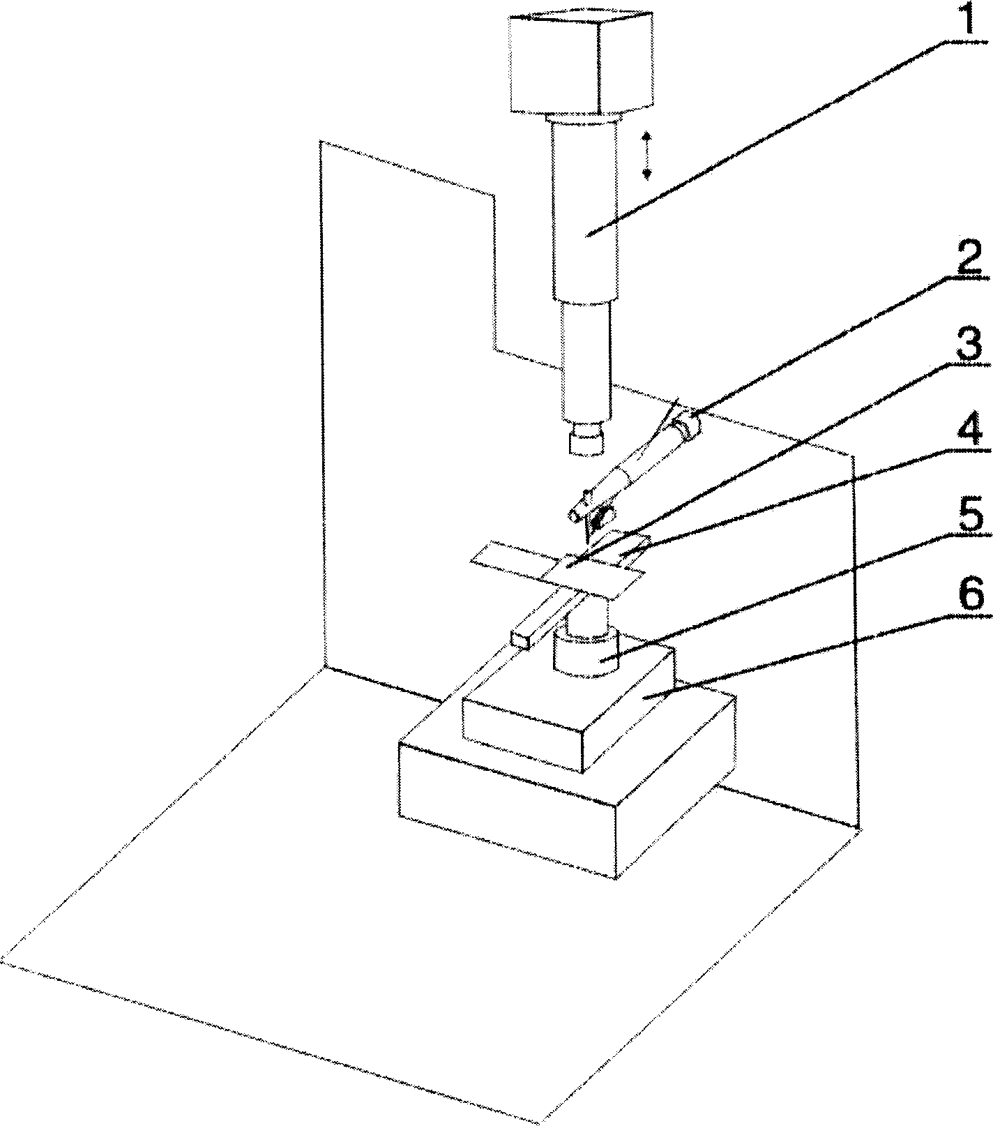
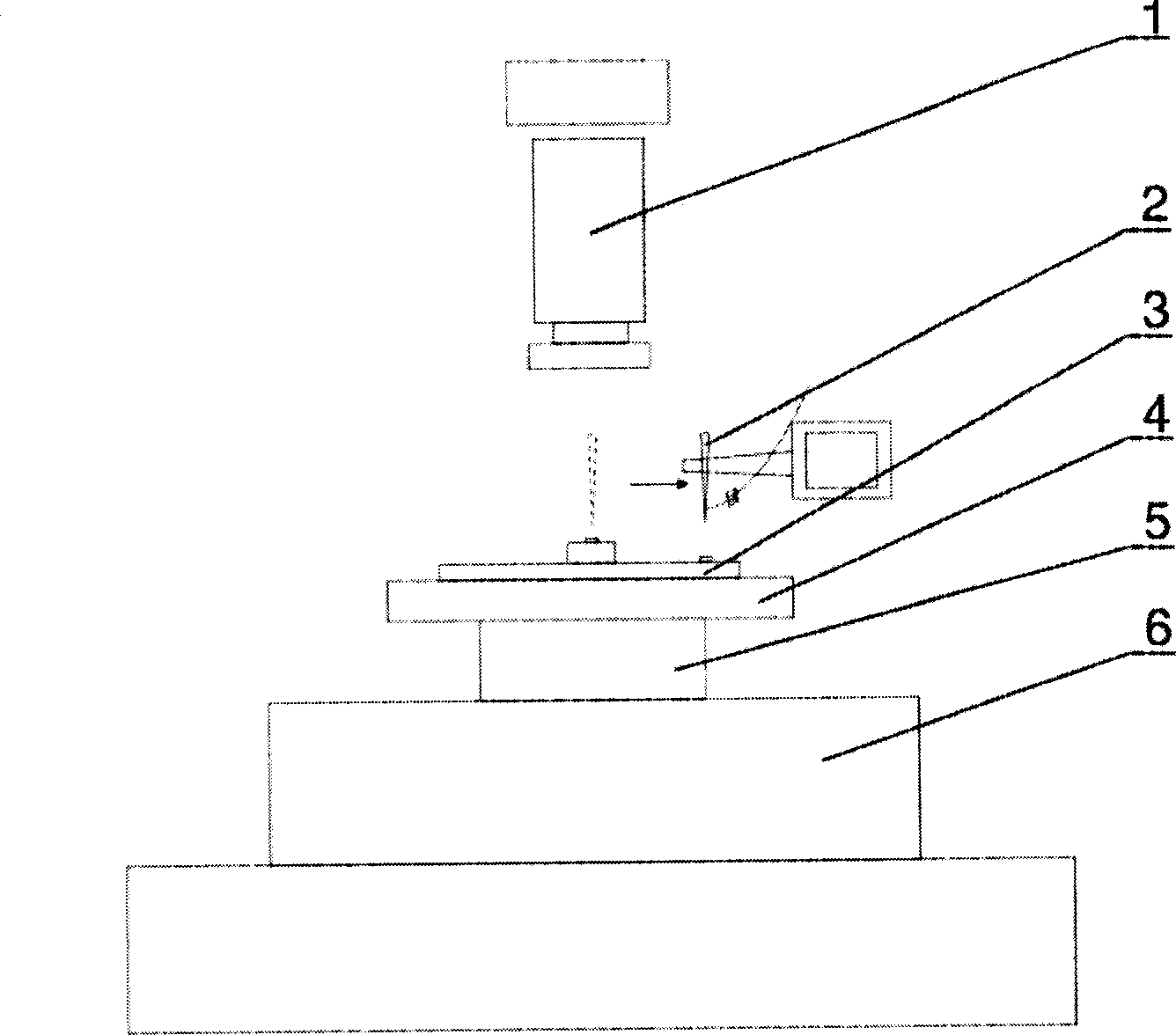
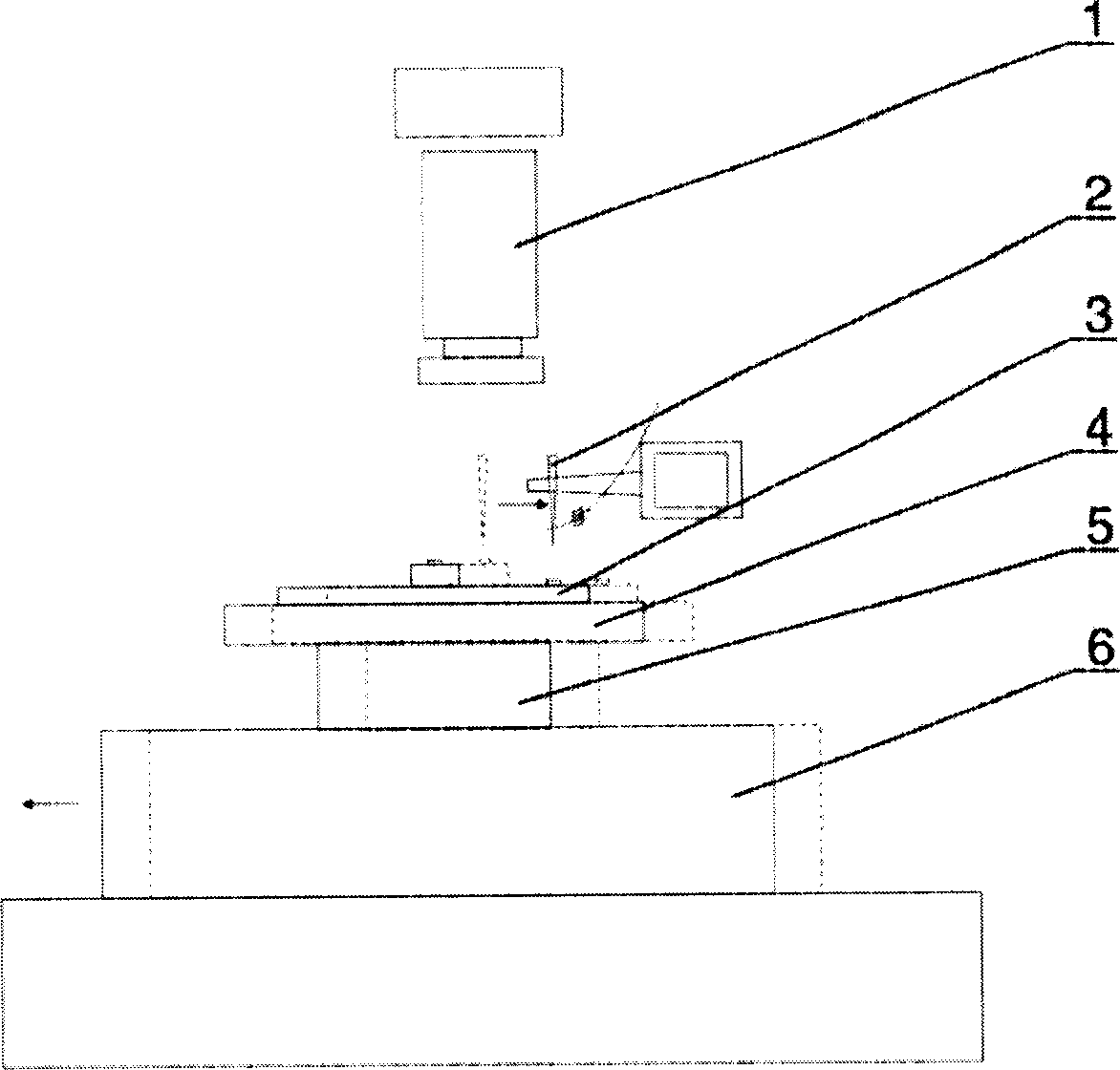
[0050] A rotary automatic ultrasonic wire welding machine such as figure 1 , 2 , 3, including a welding head system 2 with a transducer, a wire clip, a welding tip, a welding arm and wire feeding and pulling parts, and an image optical system 1 for positioning an adjustable optical lens group and a camera, A worktable 6 that can move in the horizontal direction, a turntable 5 that can rotate in the horizontal direction on the worktable 6 , and a clamp 4 that is arranged on the turntable 5 and is used to fix the workpiece 3 to be welded. The welding head system 2 is located above the center of the workbench 6 and can move vertically or horizontally. The image optical system 1 is also an image optical system for detection and is also located above the center of the workbench 6. Move in the vertical direction.

[0051] The welding head system 2 uses position signals fed back by independent vertical and horizontal positioning sensors, and the micro-controller servo board gives a...


PUM


Abstract

This invention discloses ultrasonic welding wire method and its device, which comprises welding probe system, positioning and testing cameral optics system, movable workbench, rotation bench in level direction and the clamper for welding parts fixed on the rotation bench. The method orderly comprises the following steps: setting initial positions, welding wire points; moving the initial points of welding mouth or moving the end points of welding mouth and wires; welding the wire end terminals.

Description

technical field [0001] The present invention relates to a welding method or equipment suitable for semiconductors, solid devices or parts thereof used for conducting electric current leads, in particular to an ultrasonic wire welding method and a wire welding device. Background technique [0002] The integrated circuit chip IC or light-emitting diode LED is directly packaged on the circuit board PCB or the chip on the substrate (Chip on Board, referred to as COB), which has been widely used in such as computers, mobile phones, optical digital products, smart cards, clocks, Toys and other consumer electronic information products. Wire bonding is the basic process of COB, which requires the use of ultrasonic wire bonding methods and corresponding equipment. The existing automatic ultrasonic wire bonding machine is specially used for bridging IC chips or LEDs with the corresponding pads on the PCB, including a welding head system with transducers, wire clamps, welding nozzles,...

Claims


Application Information

Patent Timeline
Patent Type & Authority Applications(China)
IPC IPC(8): H01L21/607
CPCH01L24/78H01L24/85H01L2224/78H01L2224/78313H01L2224/85H01L2224/85205H01L2924/00014H01L2924/14H01L2224/48H01L2924/00H01L2924/00012
Inventor 陈卢坤
Owner ITM SHENZHEN
Why Eureka
Try Eureka