Rotor pump

A rotor pump and rotor technology, applied in the direction of pumps, rotary piston pumps, rotary piston machines, etc., can solve the problems of complex processing technology, increased displacement, unreliable sealing, etc., to achieve low noise, reduce loss, extend The effect of service life

Inactive Publication Date: 2005-12-14
云晓璎
View PDF0 Cites 19 Cited by
  • Summary
  • Abstract
  • Description
  • Claims
  • Application Information

AI Technical Summary

Problems solved by technology

[0002] Although the existing rotor pumps have advantages that cannot be compared with other pumps, due to the disadvantages of complex processing technology and relatively unreliable sealing, especially when the volume increases, the stability of the mechanical structure and the reliability of the sealing are greatly reduced, and it is more difficult to install Improved volumetric efficiency and increased displacement
The main reasons for the above shortcomings are that the movable stopper that separates the high-pressure chamber and the low-pressure chamber has a small range of motion, poor manufacturability and reliability, and it is difficult to eliminate mechanical vibration and noise. Especially when the volume displacement is increased, the processing technology is more difficult. hard to accomplish

Method used


Image

  • Rotor pump
  • Rotor pump
  • Rotor pump

Examples


Embodiment Construction

[0024] Realize the preferred embodiment of the present invention:

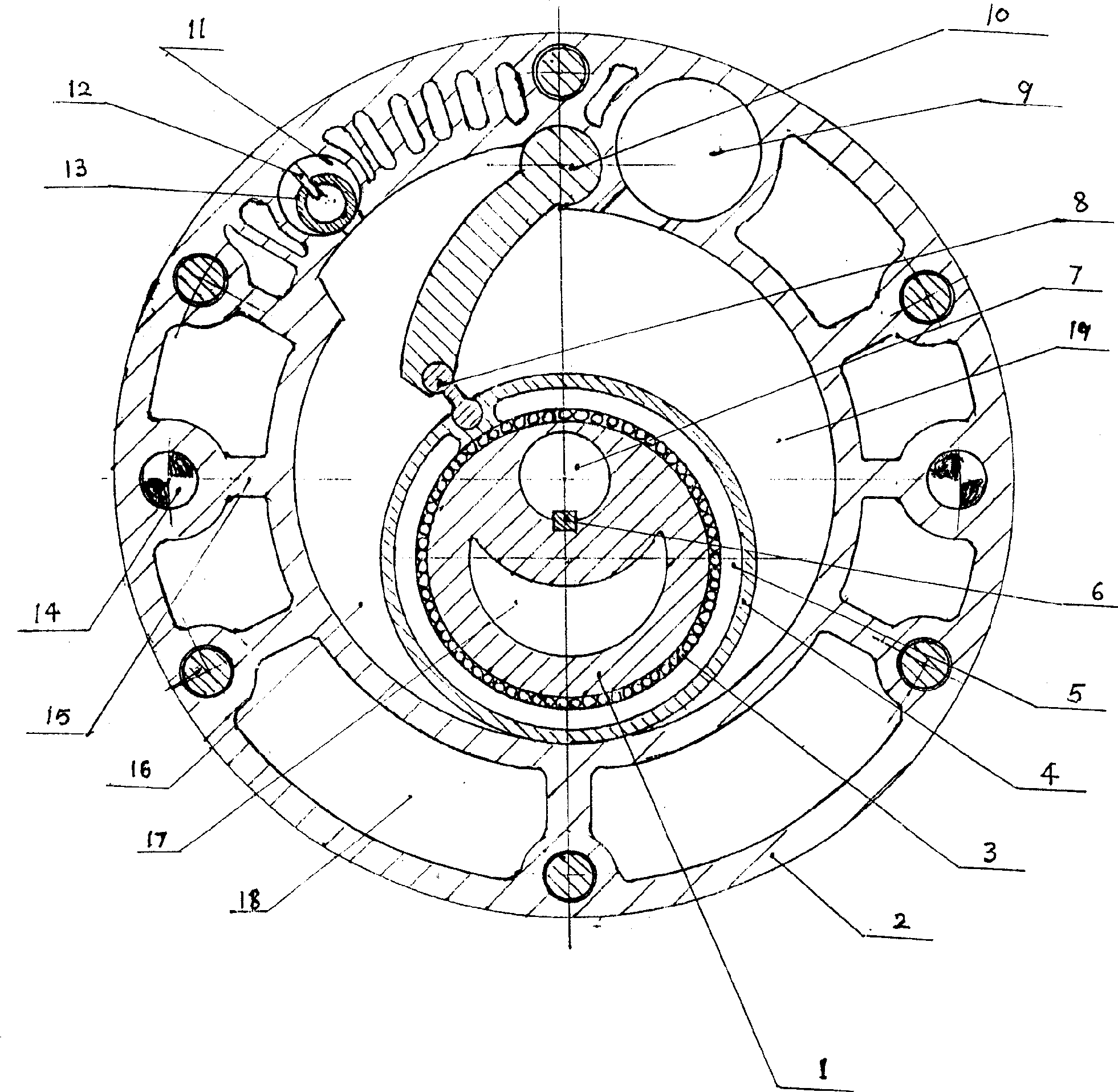
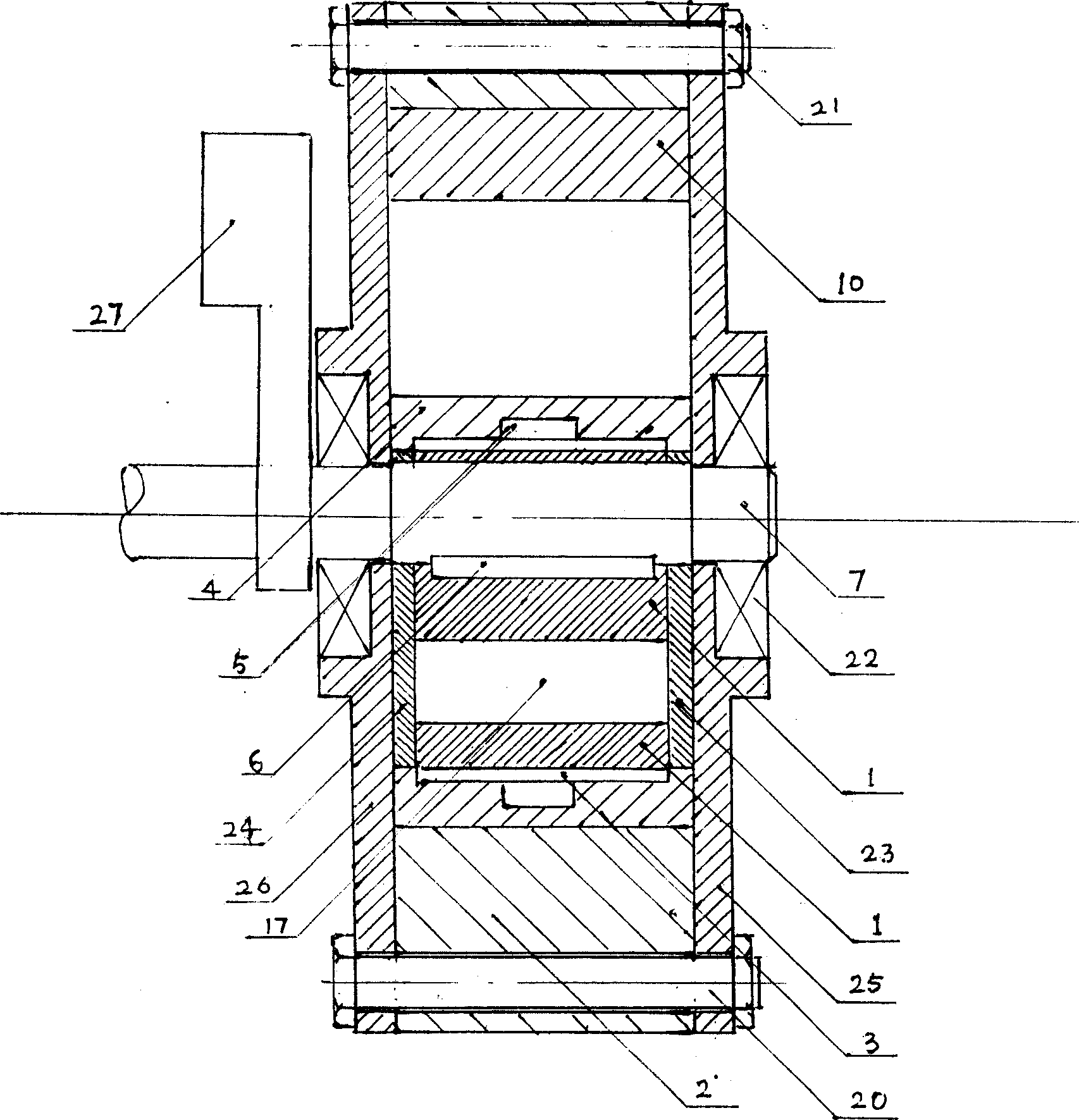
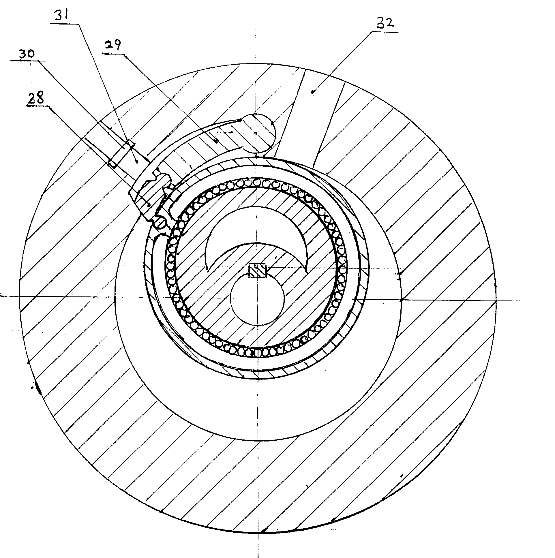
[0025] like figure 1 and figure 2 As shown, the rotor pump of the first embodiment of the present invention has a barrel-shaped cylinder stator 2, a moving ring 4, a rolling bearing 20 between the moving ring 4 and the rotor 1, and an eccentric rotor 1 that rotates around the axis. The rotor 1 is positioned in the circumferential direction on the shaft 7 by the key 6; the moving ring 4 on the rotor 1 is positioned as figure 1 In the way shown, the closed crescent-shaped cavity is divided into a high-pressure chamber 19 and a low-pressure chamber 16 through the interlocking movement of the stopper 10 and the joint 8, which is sucked by the suction port 9 of the low-pressure chamber, and then the sucked fluid is drawn from the discharge chamber through rotation. Exit 11 discharges.

[0026] combine figure 1 , figure 2 , image 3 , Figure 4 , Figure 5 , Image 6 , Figure 7 , Figure 8 , Figure 9...


PUM


Abstract

The present invention provides one kind of rotor pump. The rotor pump includes one stator inside cylinder; one front stator end cap and one back stator end cap concentric with the cylinder; one eccentric rotor assembly comprising rotator, movable ring, rolling bearing and movable sealing end caps; and one separator between the high pressure cavity and the low pressure cavity with integrated rotating shaft and arc block, and one or several movable joints.

Description

technical field [0001] The invention relates to an energy conversion device for converting mechanical energy into pressure energy, in particular to a rotor pump. Background technique [0002] Although the existing rotor pumps have advantages that cannot be compared with other pumps, due to the disadvantages of complex processing technology and relatively unreliable sealing, especially when the volume increases, the stability of the mechanical structure and the reliability of the sealing are greatly reduced, and it is more difficult to install Improve volumetric efficiency and increase displacement. The main reasons for the above shortcomings are that the movable stopper separating the high-pressure chamber and the low-pressure chamber has a small range of motion, poor manufacturability and reliability, and it is difficult to eliminate mechanical vibration and noise. Especially when the volume displacement is increased, the processing technology is more difficult. hard to ac...

Claims


Application Information

Patent Timeline
Patent Type & Authority Applications(China)
IPC IPC(8): F04C18/356
Inventor 云晓璎
Owner 云晓璎
Why Eureka
Try Eureka