
Low-power consumption permanent magnetic offset mixed radial magnetic bearing

A permanent magnet bias and hybrid radial technology, applied in the direction of bearings, shafts and bearings, mechanical equipment, etc., can solve the problems of large reluctance, large volume, and large power consumption of permanent magnets, and reduce copper consumption and power consumption. Consumption, the effect of low iron consumption

Inactive Publication Date: 2005-12-14
BEIHANG UNIV
View PDF0 Cites 20 Cited by
  • Summary
  • Abstract
  • Description
  • Claims
  • Application Information

AI Technical Summary

Problems solved by technology

[0002] The key to low power consumption of the permanent magnet electromagnetic hybrid magnetic bearing is to ensure that the magnetic flux generated by the electromagnetic coil does not pass through the permanent magnet, but the existing permanent magnet bias hybrid magnetic bearing structure is based on the ordinary radial electromagnetic bearing, along the A permanent magnet is placed axially in the stator, and the magnetic flux generated by the control coil must pass through the permanent magnet. Due to the large reluctance of the permanent magnet, a large excitation current is required for the control coil to generate a certain electromagnetic flux density. Therefore, the existing permanent magnet Offset hybrid magnetic bearings consume a lot of power, are bulky and heavy

Method used


Image

  • Low-power consumption permanent magnetic offset mixed radial magnetic bearing
  • Low-power consumption permanent magnetic offset mixed radial magnetic bearing

Examples


Embodiment Construction

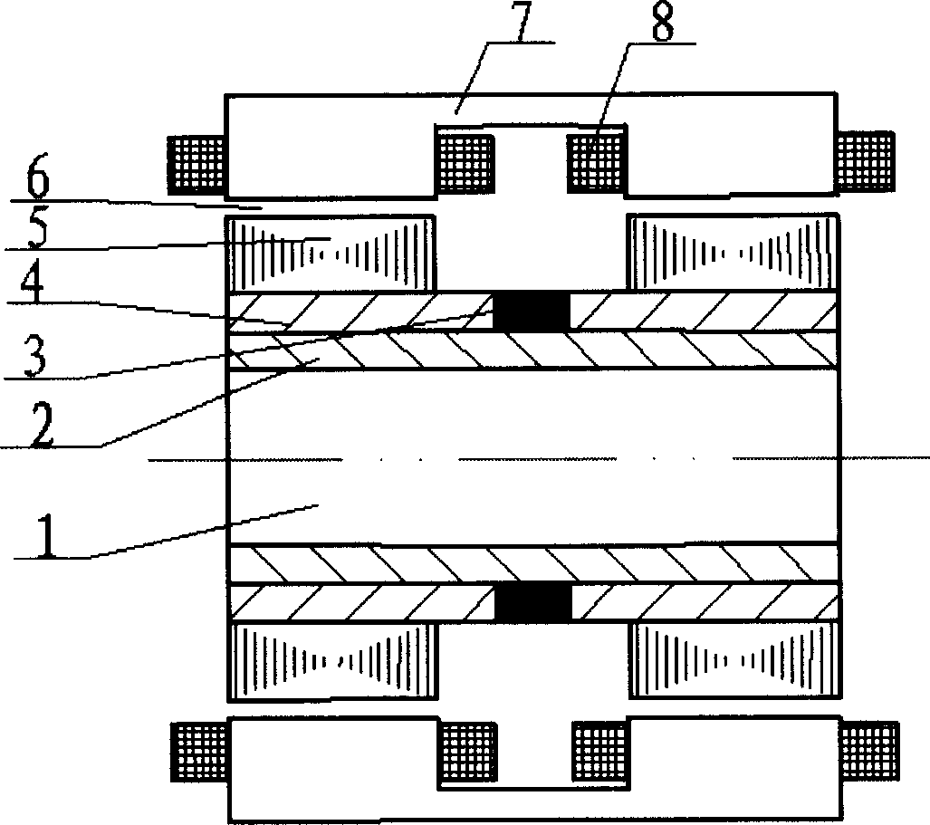
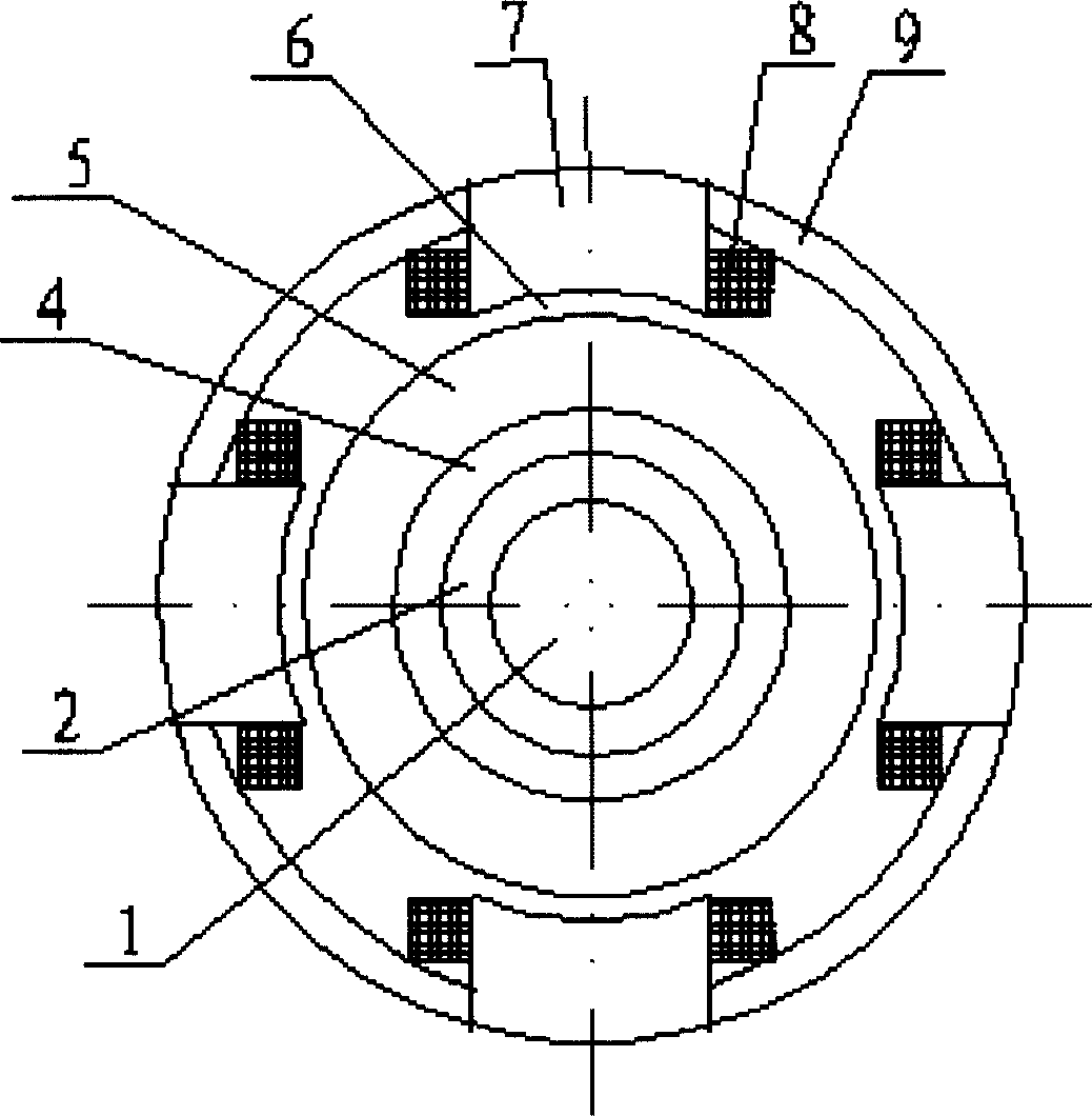
[0009] Such as figure 1 , figure 2 As shown, the present invention generally consists of left and right sets of stators and rotors. There is an air gap 6 between the stators and rotors. Each stator core yoke 7 spans the left and right ends and forms a magnetic pole at each end. Four stator core yokes 7 Orthogonally placed, respectively connected in two sections to form 4 magnetic poles of ±X axis and ±Y axis, such a magnetic bearing has 8 magnetic poles in total, and the left and right groups are respectively 4 magnetic poles. Between the stator core yoke 7 in the X-axis direction and the Y-axis direction is the stator pole spacing magnet 9, and the stator coil 8 is wound on the stator core yoke 7; the rotor includes a rotating shaft 1, a permanent magnet 3, a magnetic sleeve 4, and a rotor core 5. On the outside of the rotating shaft 1 are two magnetically conductive magnetic sleeves 4 and permanent magnets 3. The two magnetically conductive sleeves 4 sandwich the permanent...


PUM


Abstract

The permanent magnetic offset mixed radial magnetic bearing with low power consumption features that it consists of stator and rotor with air gap in between. The stator includes 8 stator magnetic poles and they forms 4 pairs in both right and left ends and separately for positive and negative directions in X and Y directions. Each stator magnetic pole consists of stator magnetic pole core and stator winding on the core, and 4 stator core yokes are connected across between two stator cores each to constitute the 8 stator magnetic poles, with magnetic isolators being set between the stator core yoke for X direction and that for Y direction. The rotor includes rotation shaft, permanent magnet, magnetizing sleeve and rotor core. The present invention has separated permanent magnetic path and electromagnetic part, lowered control current and control power consumption, small volume and light weight.

Description

Technical field [0001] The invention relates to a non-contact magnetic suspension bearing, in particular to a low-power permanent magnet bias hybrid radial magnetic bearing, which can be used as a non-contact support for rotating parts in mechanical equipment such as motors and machine tools. Background technique [0002] The key to low power consumption of the permanent magnet electromagnetic hybrid magnetic bearing is to ensure that the magnetic flux generated by the electromagnetic coil does not pass through the permanent magnet, but the existing permanent magnet bias hybrid magnetic bearing structure is based on the ordinary radial electromagnetic bearing, along the A permanent magnet is placed axially in the stator, and the magnetic flux generated by the control coil must pass through the permanent magnet. Due to the large reluctance of the permanent magnet, a large excitation current is required for the control coil to generate a certain electromagnetic flux density. Th...

Claims


Application Information

Patent Timeline
Patent Type & Authority Applications(China)
IPC IPC(8): F16C32/04
Inventor 房建成马善振孙津济郦吉臣
Owner BEIHANG UNIV
Learn More