W-shape flame furnace with gradation coal burner

A combustion device, thick and thin pulverized coal technology, applied to the flame furnace. It can solve problems such as poor adaptability of coal types, poor flame stability, and slagging

Active Publication Date: 2005-12-14
HARBIN INST OF TECH
View PDF0 Cites 17 Cited by
  • Summary
  • Abstract
  • Description
  • Claims
  • Application Information

AI Technical Summary

Problems solved by technology

Since the center of the furnace is a high-temperature area, the airflow of light pulverized coal is injected near the high-temperature area, and the airflow of dense pulverized coal is injected into the low-temperature area near the side wall, so no high-temperature and high-concentration area is formed, and the pulverized coal cannot be ignited in time. At the same time, due to the inability to form a high-temperature and high-concentration region, the flame stability is not good, the ability to stably burn under low load is low, and the adaptability of coal types is poor.
And because the dense pulverized coal flow is close to the side wall, slagging and high-temperature corrosion also occur, which seriously affects the availability and thermal efficiency of the boiler, threatening the reliability of the boiler

Method used


Image

  • W-shape flame furnace with gradation coal burner
  • W-shape flame furnace with gradation coal burner
  • W-shape flame furnace with gradation coal burner

Examples


specific Embodiment approach 1

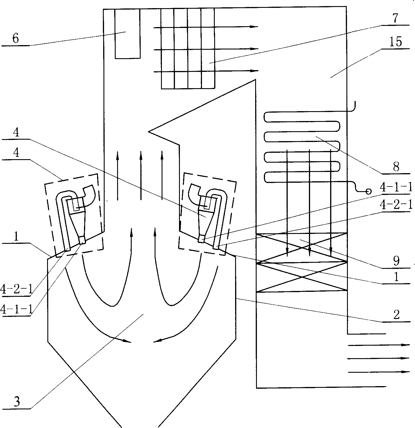
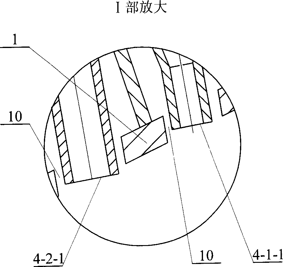
[0005] Specific embodiment 1: This embodiment includes a furnace arch 1, a side wall 2, a furnace 3 surrounded by a furnace arch 1 and a side wall 2, and a burner 4, and the burner 4 includes a burner 4-1 with a dense coal powder flow -1 and light coal powder flow burner 4-2-1, the thick coal powder flow burner 4-1-1 is arranged near the center of the furnace 3, and the light coal powder flow burner 4-2-1 is close to the side wall 2 set up. Since the burner 4-1-1 of the dense coal powder flow is close to the center of the furnace 3, the injected dense coal gas flow is close to the high temperature area in the center of the furnace. The purpose of timely ignition and stable combustion. Since the light coal powder flow nozzle 4-2-1 is close to the side wall 2, the injected light coal powder flow is close to the side wall of the furnace, thereby forming an oxidizing atmosphere near the water wall, which greatly increases the melting temperature of the ash , to avoid slagging of...

specific Embodiment approach 2

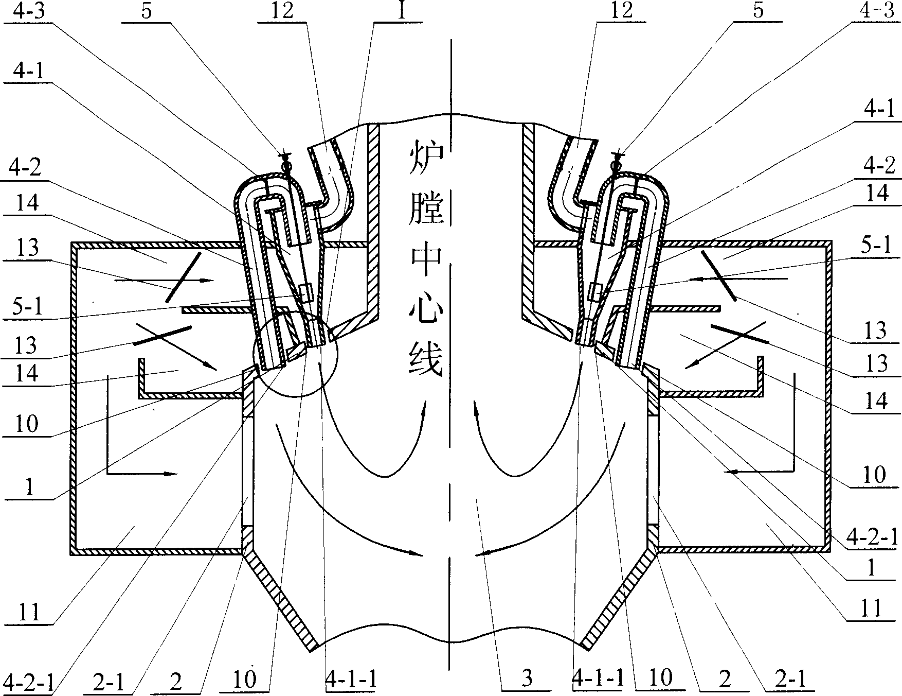
[0006] Specific embodiment two: In addition to the problems of unstable combustion, furnace wall slagging and high-temperature corrosion, existing combustion devices also have NO x The effect of reducing emissions is not obvious. refer to figure 2 , the burner 4 of this embodiment is formed by connecting the cyclone 4-1 and the exhaust pipe 4-2, the lower end of the cyclone 4-1 is a burner 4-1-1 for the dense coal powder flow, and the exhaust The lower end of the trachea 4-2 is a light coal powder flow burner 4-2-1, and the thick coal powder flow burner 4-1-1 and the light coal powder flow burner 4-2-1 are all arranged on the furnace arch 1 Above, wherein, the dense coal powder flow burner 4-1-1 is close to the center of the furnace 3, the light coal powder flow burner 4-2-1 is close to the side wall 2, and the cyclone 4-1 is equipped with a blade 5 -1 adjustment lever 5 to adjust the air swirl degree. The gap between the outlet of the light pulverized coal air flow burner...

specific Embodiment approach 3

[0008] Specific implementation mode three: refer to image 3 , the thick pulverized coal air flow burner 4-1-1 of the present embodiment is arranged on the furnace arch 1, and the light pulverized coal air flow burner 4-2-1 is arranged on the side wall 2, thereby making the thick pulverized coal flow The distance between burner 4-1-1 and light coal powder air flow burner 4-2-1 is further increased, which delays the mixing of airflow and further strengthens the effect of thick and thin combustion.


PUM


Abstract

The present invention is one W-shaped flame furnace with dense and dilute coal powder combustion and relates to one kind of burning plant. The improved W-shaped flame furnace includes furnace arch, side wall, hearth formed with the furnace arch and the side wall, and burner. The burner includes dense coal powder flow flame nozzle in the center of the hearth and dilute coal powder flow flame nozzle near the side wall. The present invention has greatly raised ash melting temperature to avoid slagging of the water cooled wall and prevent high temperature corrosion while reaching the aims of timely igniting and stable combustion.

Description

Technical field: [0001] The invention relates to a combustion device, in particular to a flame furnace. Background technique: [0002] W-shaped flame combustion technology is a combustion technology specially designed for burning low volatile coal, which can promote the burnout of pulverized coal by increasing the flame stroke. This technology has been adopted by the boilers of some domestic power plants. As for the burner on the boiler, many power plants use a cyclone-separated circular thick and thin coal pulverized combustion device with a circular burner. The burner is located on one side of the hearth center. Since the center of the furnace is a high-temperature area, the airflow of light pulverized coal is injected near the high-temperature area, and the airflow of dense pulverized coal is injected into the low-temperature area near the side wall, so no high-temperature and high-concentration area is formed, and the pulverized coal cannot be ignited in time. At the ...

Claims


Application Information

Patent Timeline
Patent Type & Authority Applications(China)
IPC IPC(8): F23C5/14
Inventor 李争起任枫高继慧邱朋华秦裕琨
Owner HARBIN INST OF TECH
Why Eureka
Try Eureka