Distribution line fault monitoring system

A technology for fault monitoring and power distribution lines, applied in the direction of information technology support systems, measuring electricity, measuring devices, etc., can solve the problems of no remote monitoring equipment installed in distribution stations, simple structure, etc., achieve support functions, improve reliability, The effect of strong real-time communication

Active Publication Date: 2005-12-14
SHANGHAI ELECTRIC POWER COMM +1
View PDF0 Cites 26 Cited by
  • Summary
  • Abstract
  • Description
  • Claims
  • Application Information

AI Technical Summary

Problems solved by technology

However, some early-built distribution stations, such as Type 1, Type 2, and Type 3 distribution stations, ha

Method used


Image

  • Distribution line fault monitoring system
  • Distribution line fault monitoring system
  • Distribution line fault monitoring system

Examples


Embodiment Construction

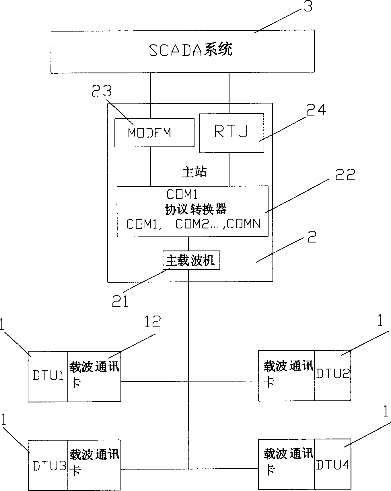
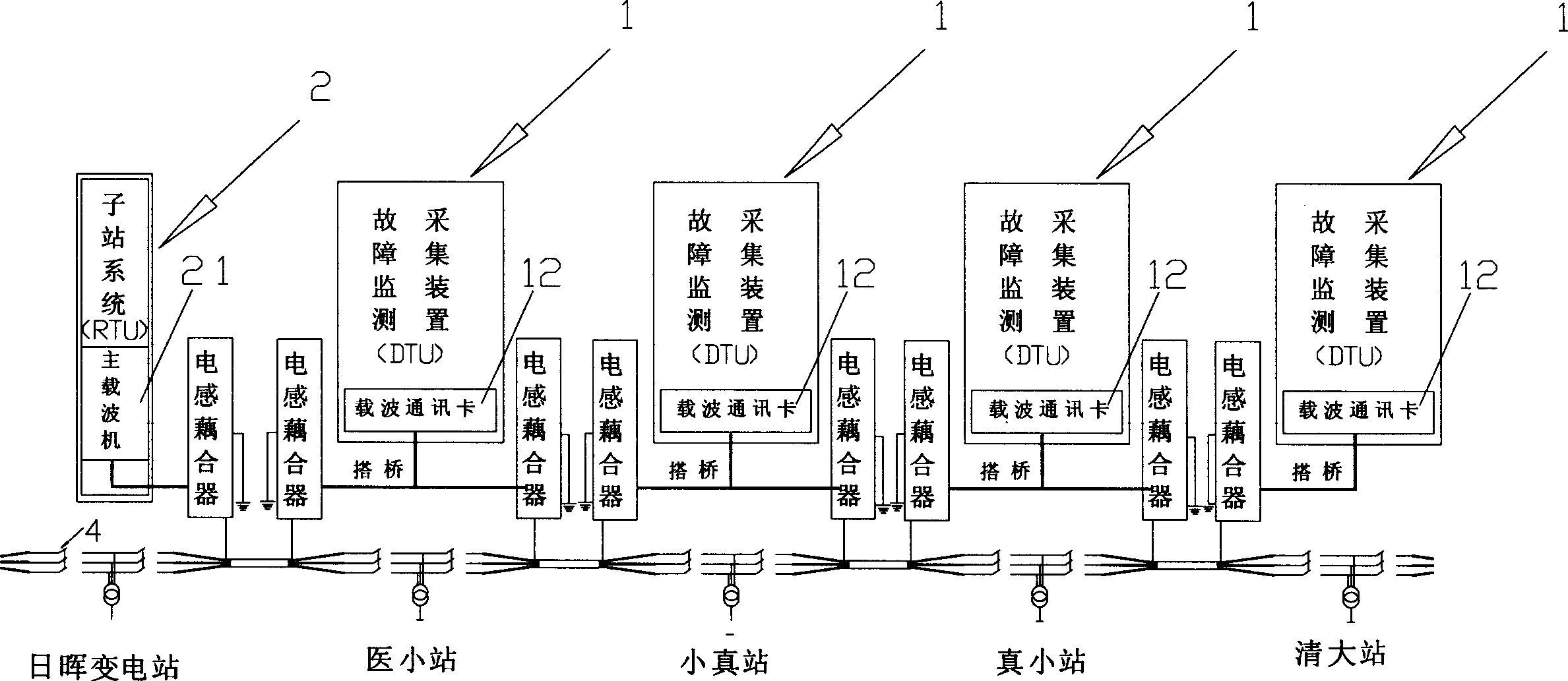
[0016] Such as figure 1 As shown, the present invention, that is: a distribution line fault monitoring system, includes four monitoring points 1 and a master station 2 that communicates with each monitoring point 1 using carrier communication (that is: connecting with a power cable).

[0017] A main carrier machine 21 , a protocol converter 22 , and an inductive coupler are installed in the main station 2 . A DTU containing a carrier communication card 12 and an inductive coupler are installed in the monitoring point 1 .

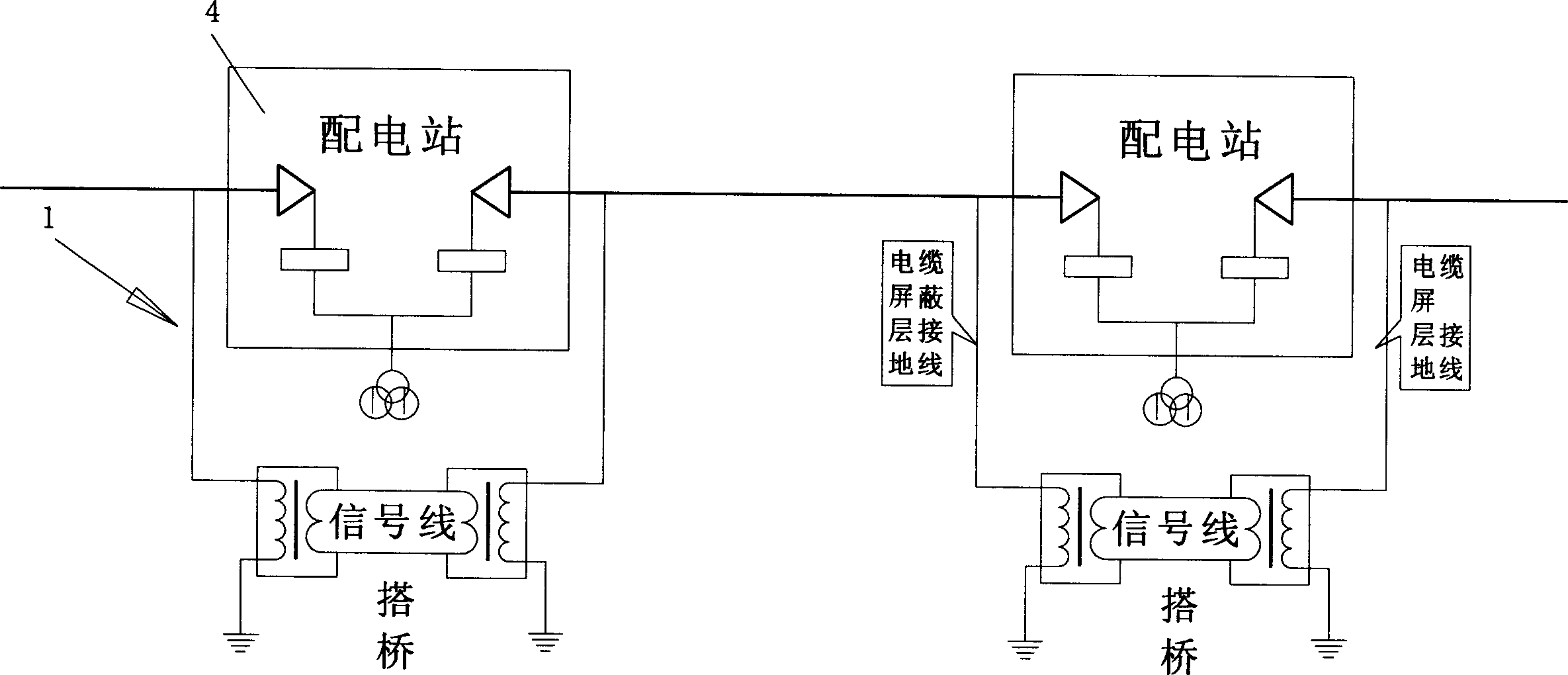
[0018] The carrier communication card 12 of each monitoring point 1 modulates the data collected by the DTU, and then couples the modulated signal to the shielding layer of the power cable through an inductive coupler.

[0019] The main carrier machine 21 adopts the 101 protocol to collect the data in the monitoring point 1, transmits the modulation signal output by each monitoring point 1 to the main station 2 through the shielding layer of the power cable...


PUM


Abstract

The fault monitoring system for power distributing system includes monitoring sites and one main station connected via power cables to the monitoring sites. In each of the monitoring sites, there are DTU with built-in carrier communication card and inductor coupler. The carrier communication card modulates data the DTU acquires and couples the modulated signal via the coupler to the power cable shielding layer. In the main station, there are main carrier machine, protocol converter and conductive coupler. Through coupling the modulated signals to the carrier machine in the main station, demodulation and corresponding protocol conversion, the RTU in the main station transmit the signal to peripheral SCADA system for fault analysis directly or via modem. After the fault section is determined, fault isolation and restoring power transmission may be completed. The present invention can raise the reliability of the power supply system.

Description

technical field [0001] The invention relates to a power distribution line fault monitoring system. Background technique [0002] At present, telecontrol RTU (remote terminal unit) is installed in some substations and distribution stations, and the monitoring data is sent to SCADA system (commissioning automation system) through optical fiber or MODEM (modem) channel. However, some of the distribution stations built in the early stage, such as type 1, type 2 and type 3 distribution stations, have relatively simple structures, and no remote monitoring equipment is installed in the distribution stations. In order to improve the reliability of power supply, improve the timeliness of fault judgment, and speed up the speed of fault resolution, real-time monitoring of type 1, type 2, and type 3 distribution stations is also required. Contents of the invention [0003] The purpose of the present invention is to provide a power distribution line fault monitoring system, so that th...

Claims


Application Information

Patent Timeline
IPC IPC(8): G01R31/02
CPCY04S10/52
Inventor 陆融孙列张小越杜成刚杨健周静
Owner SHANGHAI ELECTRIC POWER COMM
Why Eureka
Try Eureka