Composite tool insert

一种衬片、刀具的技术,应用在刀具衬片领域,能够解决操作耗时、花掉时间等问题

Inactive Publication Date: 2005-12-28
ELEMENT SIX ABRASIVES
View PDF0 Cites 19 Cited by
  • Summary
  • Abstract
  • Description
  • Claims
  • Application Information

AI Technical Summary

Problems solved by technology

Due to the length of the drill string to be removed, the operation is time consuming and as a result a lot of time is spent

Method used


Image

  • Composite tool insert
  • Composite tool insert
  • Composite tool insert

Examples


Embodiment Construction

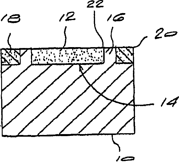
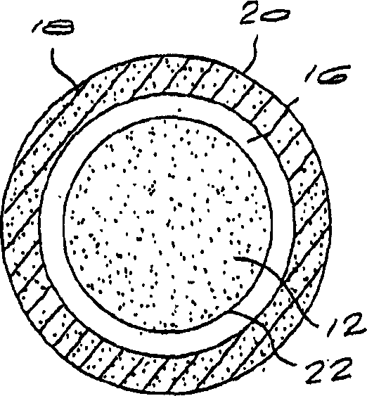
[0012] Refer to the attached figure 1 and figure 2 , the embodiment of the specific tool lining of the present invention is shown in the figure. The tool lining comprises: a tungsten carbide base layer 10; a PCD layer 12 disposed in a recess 14 and surrounded by a tungsten carbide annular portion or ring 16 extending laterally from a support surface 17; and a surrounding ring 16 protective layer or protective ring 18.

[0013] The guard ring 18 may be made of a different grade of tungsten carbide than the tungsten carbide base layer 10, or may be made of tool steel or other suitable materials. The choice of material depends on the substance or substrate to be milled, drilled or cut prior to exposing the PCD layer 12 . The guard ring 18 can be formed in situ, or as a separate ring-shaped component that fits onto the knife lining. The guard ring 18 may be bonded by brazing, press-fitting, burn-in or other convenient means to the tool lining which has been machined to receiv...


PUM


Abstract

A tool insert comprises a substrate (10) having a support surface and a support ring extending laterally from the support surface. The support ring is sized to define a recess (14) within the confines thereof and a shelf about the periphery thereof. A layer (12) of ultra-hard abrasive material is located within the recess and bonded to the substrate and the support ring (16), and presents a primary cutting edge (22) for the tool insert. A protective layer (18) is bonded to the shelf about the support ring so as to protect the primary cutting edge. The protective layer provides a secondary cutting edge (20) for the tool insert, the depth of the protective layer being selected so as to be sufficient to protect the primary cutting edge whilst cutting, milling or drilling through a first substance but to expose the primary cutting edge upon encountering a second substance.

Description

technical field [0001] The present invention relates to a tool insert. Background technique [0002] The use of diamond compacts, also known as PCDs, as cutting elements is well known in the art and is widely used in various cutting, drilling, milling and other abrasive operations because diamond cutting The knives are highly wear-resistant. But diamond cutting knives are not always suitable for all substrates encountered. As is known, diamond tools cannot be used satisfactorily for milling or drilling through ferrous substrates, such as steel. The result is that the use of diamond cutters is unsuitable when it is necessary to mill through a steel sleeve used to line a vertical borehole or shaft in a downhole drilling operation. [0003] Due to the interaction with ferrous materials, PCD is not suitable for drilling through steel casings, and a drill liner is required instead. Tungsten carbide cutters are therefore usually used in drills to mill through steel sleeves. O...

Claims


Application Information

Patent Timeline
Patent Type & Authority Applications(China)
IPC IPC(8): E21B10/56E21B10/567E21B29/06
CPCE21B10/5676E21B29/06Y10T407/19
Inventor K·汤克R·A·查普曼R·D·阿基利斯
Owner ELEMENT SIX ABRASIVES
Why Eureka
Try Eureka