
Infrared detector with micro-bridge structure and manufacturing method thereof

A technology of infrared detector and microbridge structure, which is applied in the field of micro-electromechanical, can solve the problems that affect the overall performance of infrared detectors, high resistivity, and easy electromigration, etc., to improve processing and manufacturing capabilities, improve effective area, and improve process The effect of compatibility

Active Publication Date: 2010-12-29
ZHEJIANG DALI TECH +1
View PDF0 Cites 120 Cited by
  • Summary
  • Abstract
  • Description
  • Claims
  • Application Information

AI Technical Summary

Problems solved by technology

For traditional infrared detectors with micro-bridge structures, aluminum (Al) pillars are generally used to support the micro-bridge structure, such as "Development of Amorphous Silicon Technology in CEA / LETi" (SPIE (International Society for Optical Engineering) 2002 Photodetector Materials and equipment, SPIE Vol. 4650, pp. 138-149, E MOTTIN. et al., "Amorphous silicon technology improvement at CEA / LETI," Proceedings of SPIE Photodetector Materials and Devices VII, 2002. SPIE Vol.4650, pp.138-149), this The structure has high requirements for the filling effect of aluminum in the through hole and the selective ratio of etching. In addition, the support of aluminum pillars also has problems such as high resistivity and easy electromigration, which affects the overall performance of the infrared detector; therefore, how to learn from Improving the manufacturing process of infrared detectors in the existing semiconductor process, solving the problem of flattening the surface of the MEMS process, etc., and greatly improving the yield and reliability of the product have become technical problems that need to be solved urgently in the industry.

Method used


Image

  • Infrared detector with micro-bridge structure and manufacturing method thereof
  • Infrared detector with micro-bridge structure and manufacturing method thereof
  • Infrared detector with micro-bridge structure and manufacturing method thereof

Examples


Embodiment Construction

[0047]The present invention will be further described below in conjunction with accompanying drawing:

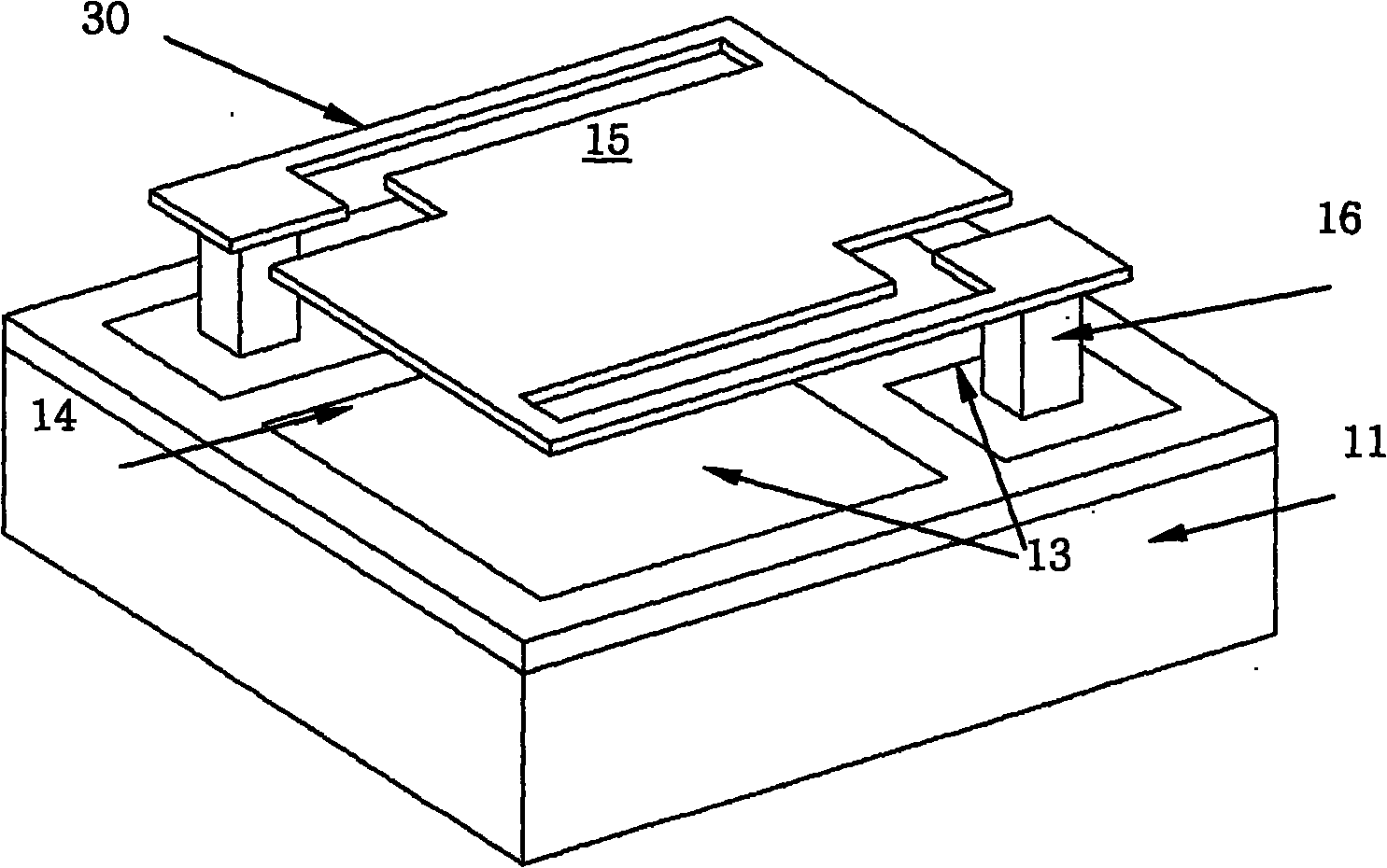
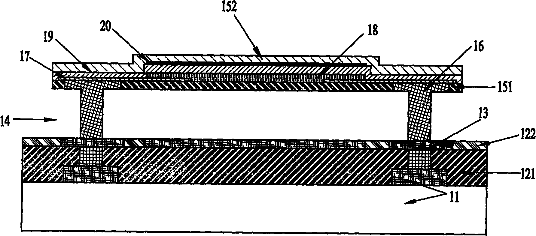
[0048] Please see figure 1 and figure 2 , This embodiment proposes an infrared detector, which is applicable to places such as power network security detection, forest fire detection, and human body temperature detection. The inventive microbridge structure can be widely used in micro-electromechanical systems and devices such as uncooled infrared detectors, gas detectors, micro-heating platforms, and infrared radiation source devices.

[0049] The infrared detector sequentially includes a readout circuit 11, a first dielectric layer 121, a metal reflection layer 13, a second dielectric layer 122, a sacrificial layer 14, a copper pillar 16, a first release protection layer 151, a metal electrode 17, and a sensitive material detection layer 18. A dielectric insulating layer 19, an infrared absorbing layer 20, and a second release protection layer 152.

[0050] The silicon...


PUM


Abstract

The invention relates to an infrared detector with a micro-bridge structure, which belongs to the technical field of micro-electromechanics, and comprises a silicon substrate as a read-out circuit of the infrared detector; a metal reflecting layer deposited on the silicon substrate; a dielectric layer which is deposited in a groove of the metal reflecting layer and has the height being consistentwith that of the metal reflecting layer; a sacrifice layer and a first release protection layer used as protection of release of the sacrifice layer which are deposited on the dielectric layer and the metal reflecting layer and form through holes by lithography and etching; a copper or tungsten pier which is deposited in the through hole of the sacrifice layer; a metal electrode deposited on the copper or tungsten pier and the first release protection layer; and a sensitive material detecting layer which is deposited on the metal electrode and the first release protection layer. A Cu-column micro-bridge structure is manufactured by using the damascene process, and a flat micro-bridge plane is manufactured by introducing the chemical mechanical polishing process (CMP), thereby being conductive to the follow-up process and improving the performances.

Description

technical field [0001] The invention belongs to the field of micro-electromechanical technology, and in particular relates to a process method for manufacturing an infrared detector focal plane array by using a Damascus copper process technology. Background technique [0002] Micro-electro-mechanical (MEMS) products have been widely used in people's daily life, including accelerometers for automotive airbags, automotive and medical pressure sensors, micro-microphones, inkjet printing heads, and uncooled, non-infrared detectors. MEMS products generally include MEMS structures and CMOS processing circuit parts. Due to the poor compatibility between MEMS and CMOS processes, it was difficult to achieve large-scale production in the early stage. In recent years, due to the gradual expansion of market demand for MEMS products, the concept of CMOS-MEMS has been gradually proposed. CMOS-MEMS is to use CMOS technology to make peripheral reading and signal processing circuits, and t...

Claims


Application Information

Patent Timeline
IPC IPC(8): B81B7/02B81C1/00G01J5/10
Inventor 池积光钱良山康晓旭姜利军
Owner ZHEJIANG DALI TECH
Learn More