

Protection of anodes for electrochemical cells
- Summary
- Abstract
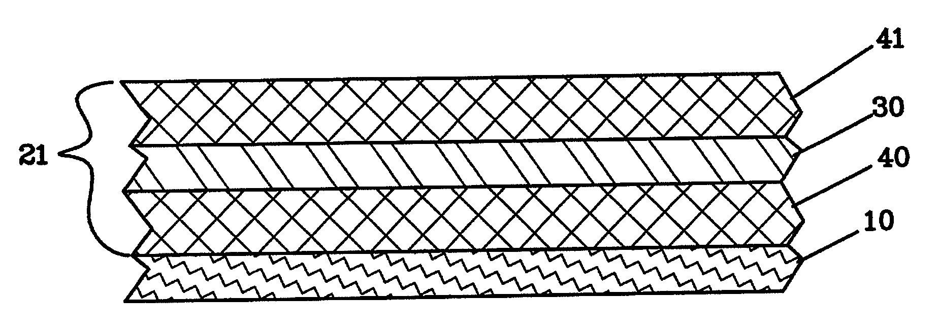
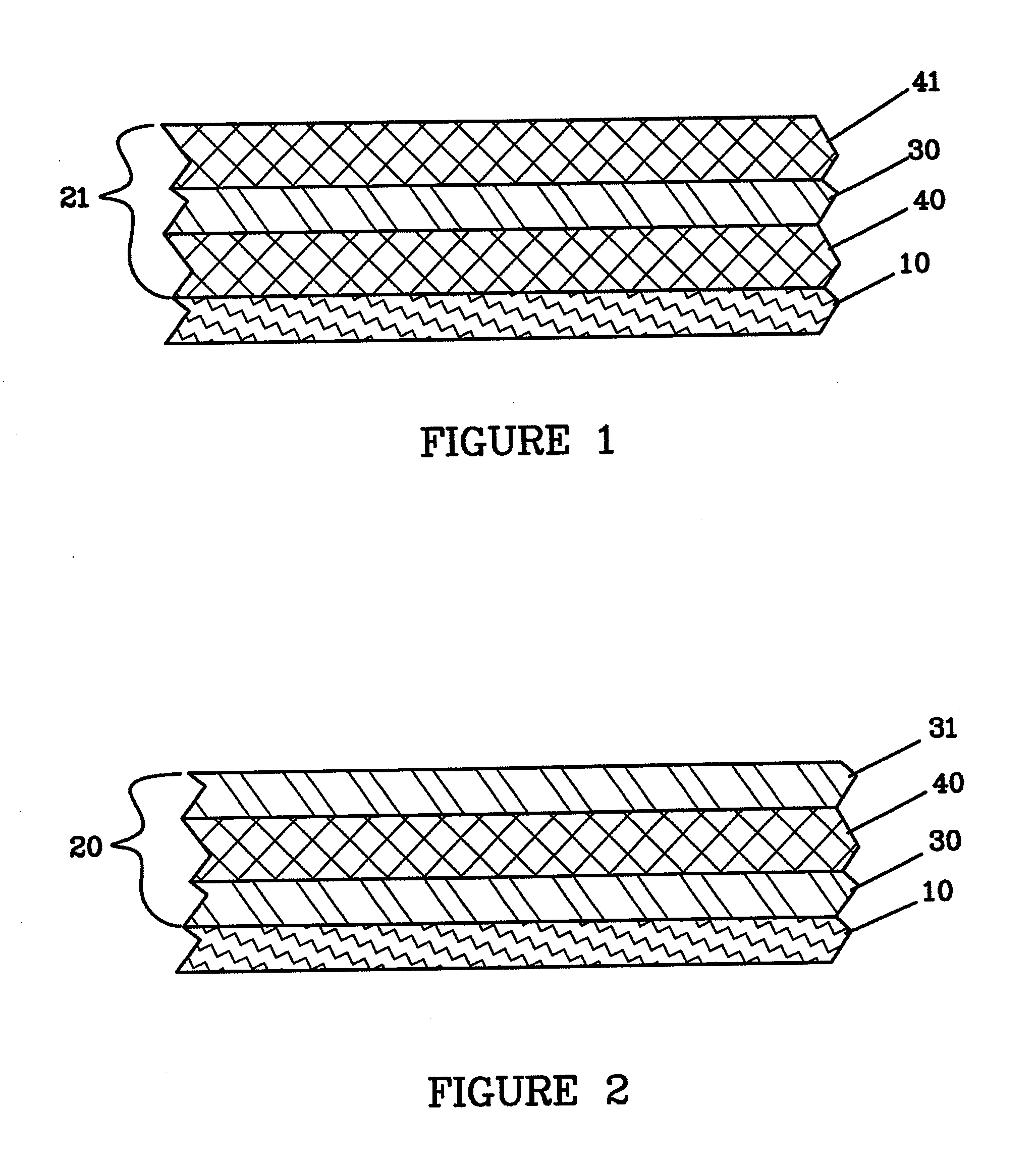
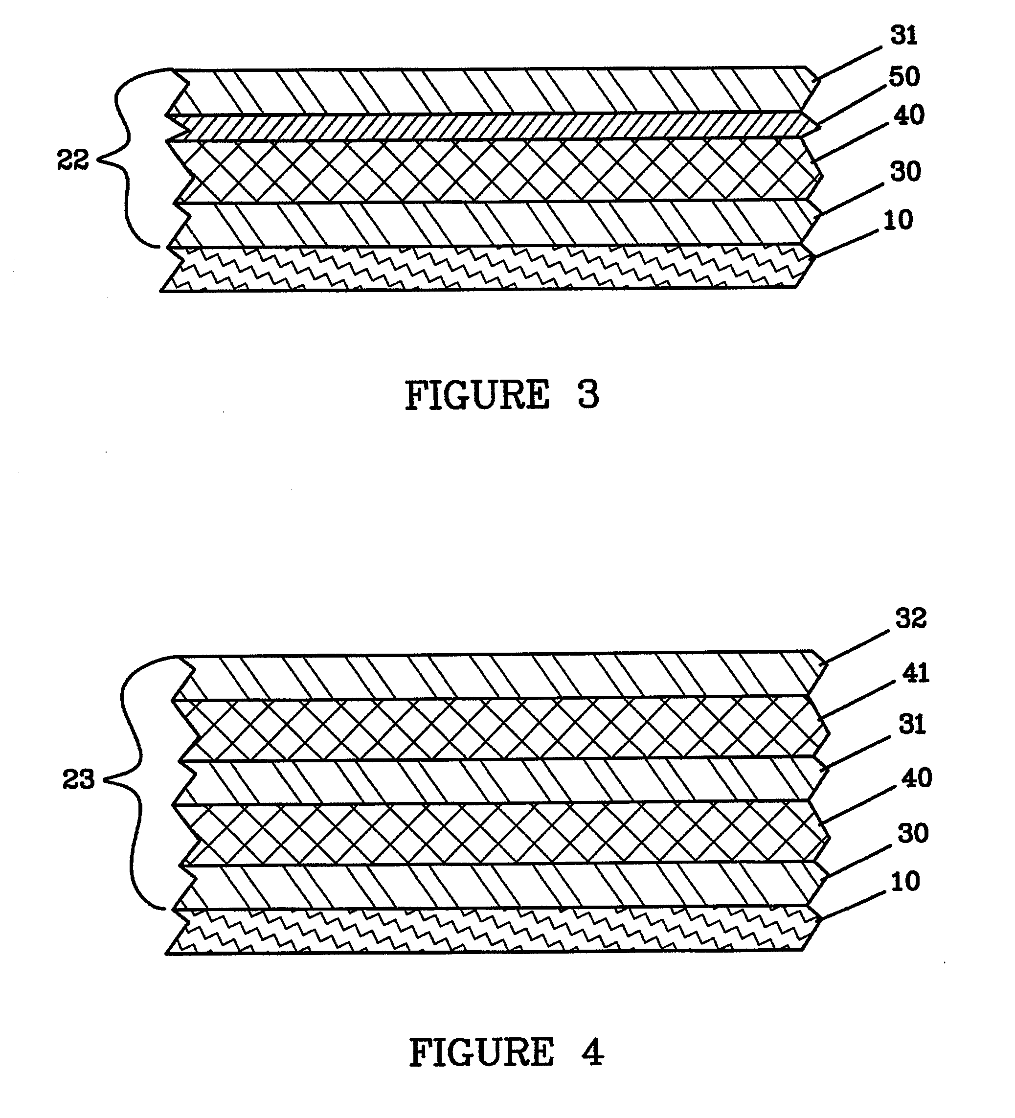
- Description
- Claims
- Application Information
AI Technical Summary
Benefits of technology
Problems solved by technology
Method used
Image

Examples
example 1
[0190]A vacuum web coating system located in a dry room, having an unwind drive, liquid cooled drum at −20° C., load cell rollers for controlling tension, a rewind drive, and two deposition zones, was loaded with an anode substrate of 23 μm PET metallized on one side with 60 nm of inconel and of 15 cm width. The chamber was evacuated to 10−6 Torr. Lithium was deposited on to the substrate by first heating a thermal evaporation lithium source to 535° C. to allow significant evaporation, and then starting the web drive at 0.5 feet per minute. The lithium evaporation was allowed to stabilize to give an 25 μm coating of lithium on the inconel of the substrate layer.
example 2
[0191]A vacuum web coating system located in a dry room, having an unwind drive, liquid cooled drum at −20° C., load cell rollers for controlling tension, a rewind drive, and two deposition zones, was loaded with an anode substrate of 23 μm PET metallized on one side with 60 nm of inconel and of 15 cm width. The chamber was evacuated to 10−6 Torn Lithium was deposited on to the substrate by first heating a thermal evaporation lithium source to 535° C. to allow significant evaporation, and then starting the web drive at 0.5 feet per minute. The lithium evaporation was allowed to stabilize to give an 25 μm coating of lithium on the inconel of the substrate layer. Immediately adjacent to the lithium source CO2 was introduced through a mass flow controller at a flow between 10 and 100 sccm raising the pressure to 0.1 to 50 mTorr. Dark discoloration was immediately seen in the co-deposited lithium with CO2 from this in situ deposition process.
example 3
[0192]A vacuum web coating system located in a dry room, having an unwind drive, liquid cooled drum at −20° C., load cell rollers for controlling tension, a rewind drive, and two deposition zones, was loaded with an anode substrate of 23 μm PET metallized on one side with 60 nm of inconel and of 15 cm width. The chamber was evacuated to 10−6 Torr. Lithium was deposited on to the substrate by first heating a thermal evaporation lithium source to 535° C. to allow significant evaporation, and then starting the web drive at 0.5 feet per minute. The lithium evaporation was allowed to stabilize to give an 25 μm coating of lithium on the inconel of the substrate layer. Immediately adjacent to the lithium source RF magnetron plasma treatment with the CO2 gas was performed. Forward RF power was between 50 and 100 W at a pressure of 0.1 to 50 mTorr. Dark discoloration was immediately seen in the co-deposited lithium with CO2 from this in situ deposition process.
PUM
 Abstract
Description
Claims
Application Information