
High speed magnetic suspension superimposition rail beam connection mechanism, rail beam and its producing method

A technology of connection mechanism and manufacturing method, applied in the field of connection mechanism of laminated track beams, to achieve the effects of simplifying the manufacturing process, improving productivity and reducing scale

Active Publication Date: 2006-01-04
TONGJI UNIV
View PDF2 Cites 23 Cited by
  • Summary
  • Abstract
  • Description
  • Claims
  • Application Information

AI Technical Summary

Problems solved by technology

[0005] The object of the present invention is to provide a high-speed maglev superimposed track beam connection mechanism, track beam and its manufacturing method, to solve the problem that the track beam includes the upper part of the functional area—the track slab and the lower foundation—the load-bearing main beam. Reliable connection, simple structure, easy manufacture, fast and convenient adjustment and positioning, and less steel consumption

Method used


Image

  • High speed magnetic suspension superimposition rail beam connection mechanism, rail beam and its producing method
  • High speed magnetic suspension superimposition rail beam connection mechanism, rail beam and its producing method
  • High speed magnetic suspension superimposition rail beam connection mechanism, rail beam and its producing method

Examples


Embodiment Construction

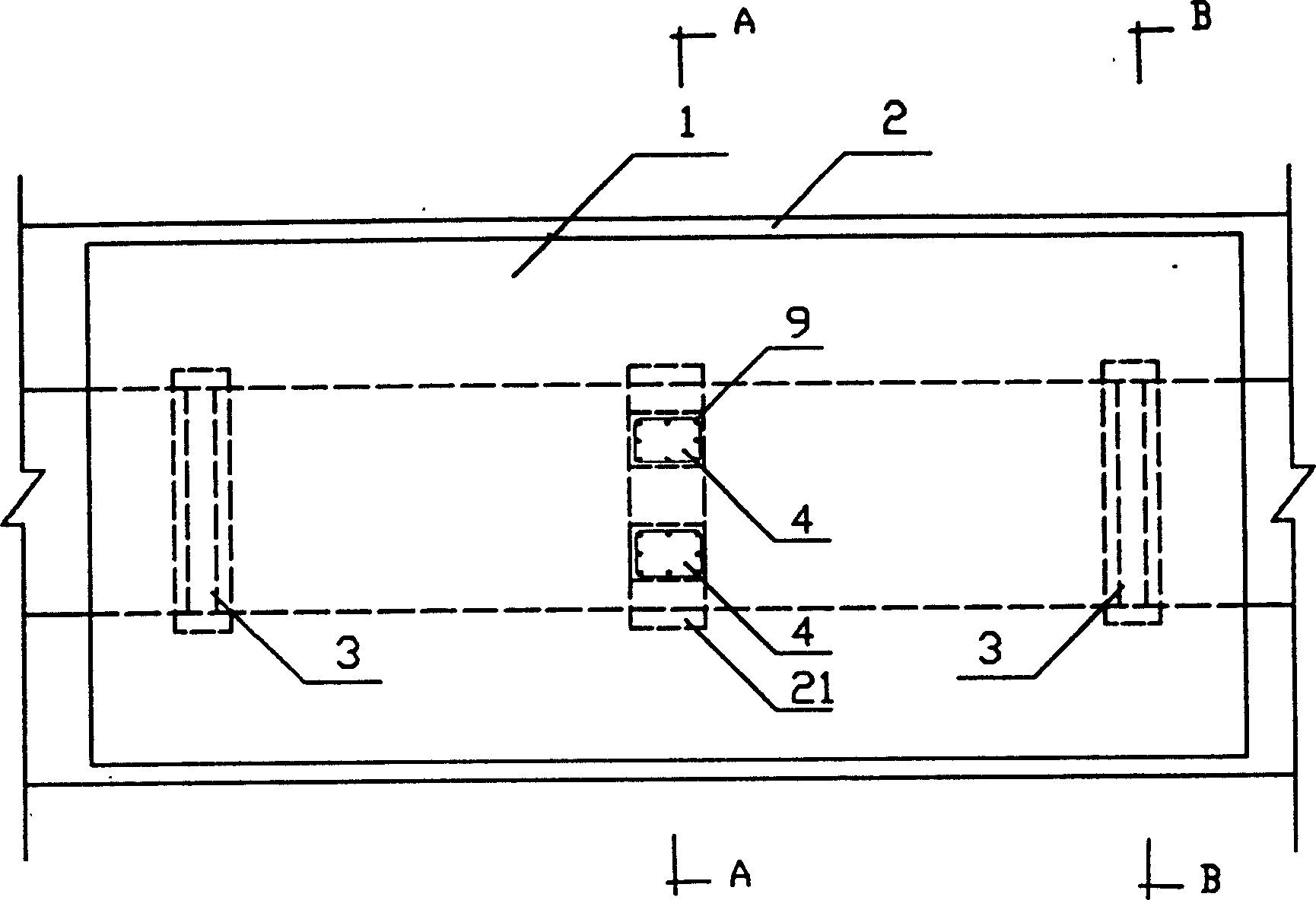
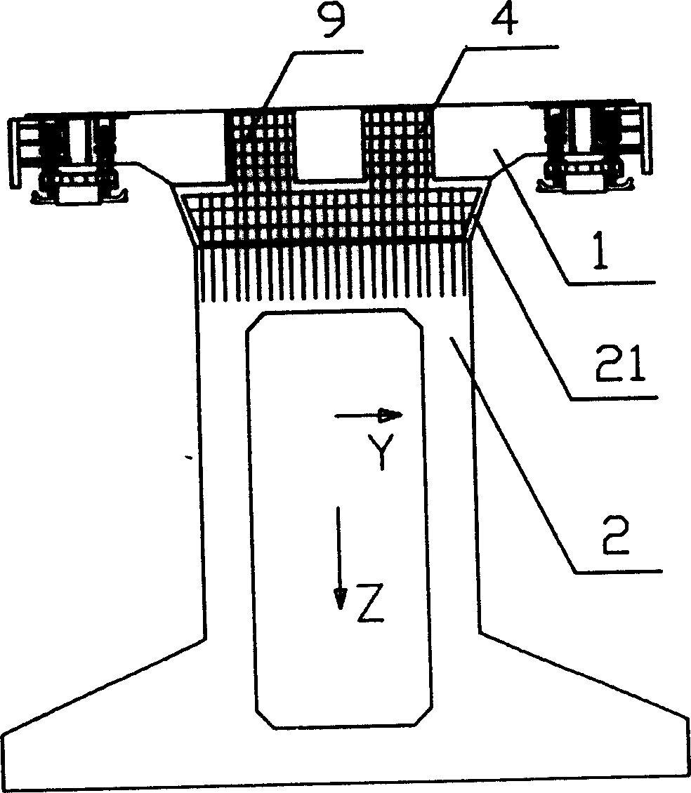
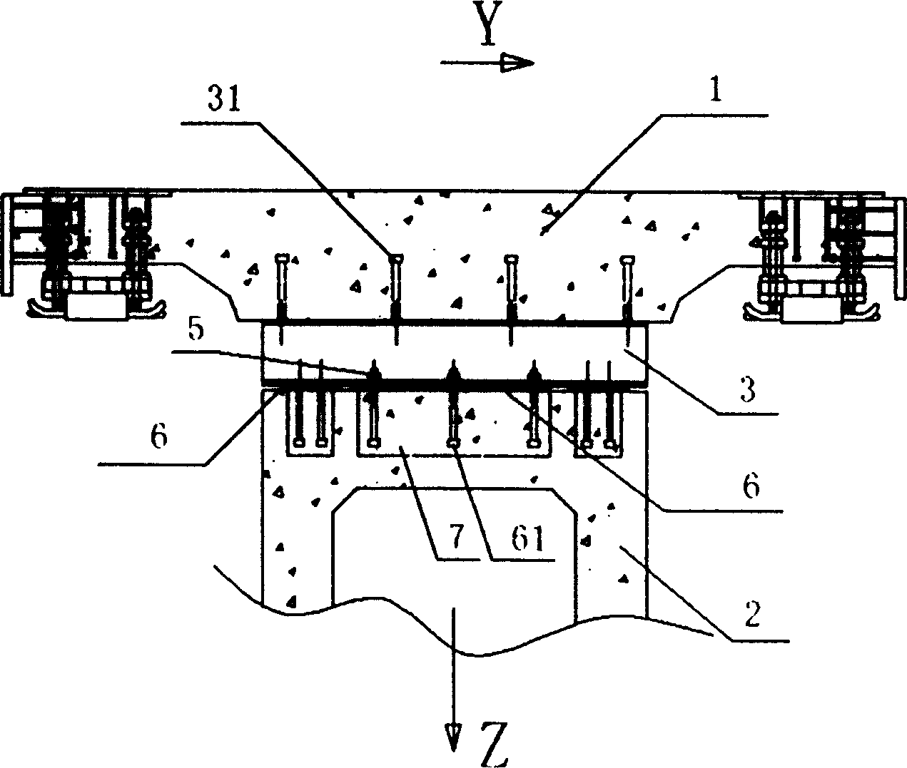
[0037] see Figure 1~3As shown, the present invention consists of two parts, the reinforced concrete grouting fixing part 4 which is located in the middle part of the track slab 1 and is connected to the load-bearing main beam 2, and the supporting steel beam 3 supported between the track slab 1 and the load-bearing main beam 2. composition. Firstly, the steel bar 9 is preset on the boss 21 of the load-bearing main beam 2. When installing on site, the steel bar 9 is inserted into the hole reserved in the middle part of the track plate 1. After the precise positioning between the track plate and the load-bearing main value, Concrete is poured into the hole to solidify into the reinforced cement grouting fixed part 4, so that the middle part of the track slab 1 is rigidly connected with the load-bearing main beam 2. The reinforced concrete grouting fixing part 4 can be arranged along the entire length of the boss 21, and can also be symmetrically divided into several parts and ...


PUM

PropertyMeasurementUnit
Heightaaaaaaaaaa

Abstract

The present invention provides high speed magnetic suspension superposing rail beam connecting mechanism, rail beam and the manufacture process. The rail beam connecting mechanism includes bearing steel beam and welded nail, and has reinforced cement grouted connecting part in the middle part of the rail plate to connect the rail plate and the main bearing beam. The H-shaped bearing steel beam is embedded with welded nail on two ends of the rail plate and is born between the rail plate and the main bearing beam. The present invention realizes the reliable connection between the upper functional area of the rail beam and the rail plate and between the lower base and the main bearing beam, and has simple structure, easy manufacture, fast and convenient regulation and location, and low steel consumption.

Description

Technical field: [0001] The invention relates to a track device along the road of an electric vehicle, in particular to a connection mechanism of a laminated track beam of a maglev train, a track beam and a manufacturing method thereof. Background technique: [0002] Railway transportation has a history of nearly 200 years. It has gradually developed from steam locomotive traction to current diesel locomotives, electric locomotives, and gas turbine locomotives. The maximum speed has reached about 200 kilometers per hour. In the newly developed conventional maglev railway, the train is suspended above the track by electromagnetic force during operation, and the maximum speed can reach 500 kilometers per hour. Existing maglev railways are generally of the elevated type, using integral or composite track beams. The top of the track beams is the functional area where the stator of the linear motor and other electrical components are installed. Small, generally only about 10mm, ...

Claims


Application Information

Patent Timeline
IPC IPC(8): E01B25/30E04B1/41
Inventor 叶丰曾国锋曹雪峰万建军李文沛朱志伟施丹陈定祥
Owner TONGJI UNIV
Learn More