Capillary electrophoretic chip with extraining sampling and its using method

A capillary electrophoresis and sample injection technology, applied in the field of chemical and biological analysis and detection, can solve the problems of affecting separation efficiency, sacrificing detection sensitivity, affecting analysis speed, etc., to improve separation efficiency, ensure detection sensitivity, and avoid background noise.

Inactive Publication Date: 2010-10-27
SHANGHAI INST OF MICROSYSTEM & INFORMATION TECH CHINESE ACAD OF SCI
View PDF5 Cites 0 Cited by
  • Summary
  • Abstract
  • Description
  • Claims
  • Application Information

AI Technical Summary

Problems solved by technology

The "double T-shaped" structure has high sensitivity due to the large amount of sample injection, but the separation efficiency is poor due to the wide sample band itself and molecular diffusion
Due to the effect of molecular diffusion and the lateral expansion of the electric field at the intersection of the "cross-shaped" structure, when the sample flows through the intersection in the injection channel during the injection phase, the sample expands to the separation channel, thus greatly It affects the separation efficiency; in order to overcome the above problems, some people apply voltage on the electrodes at both ends of the separation channel during sample injection to implement "shrink" sample injection [Jacobson, S.C.; Hergenrsder, R.; Koutny, L.B.; Warmack, R.J.; and Ramsey, J.M., "Effects of Column Geometry on the Performance of Microchip Electrophoresis Devices", Anal.Chem.66, 1107 (1994).], but this sampling method requires a long injection time, which affects the analysis speed, and the injection strip The belt is irregularly tapered, and if the detection window deviates slightly from the centerline of the separation channel, different detection results will be obtained; in addition, some people use the "narrow sample channel" mode [Zhang CX; ManzA., "Narrow sample channel injectors for capillary electrophoresis onmicrochips ″, Anal.Chem.73, 2656(2001).], but this method has sacrificed the detection sensitivity, so it also has great limitations

Method used


Image

  • Capillary electrophoretic chip with extraining sampling and its using method
  • Capillary electrophoretic chip with extraining sampling and its using method
  • Capillary electrophoretic chip with extraining sampling and its using method

Examples


Embodiment Construction

[0016] The specific implementation manner of the present invention will be further described below in conjunction with the accompanying drawings.

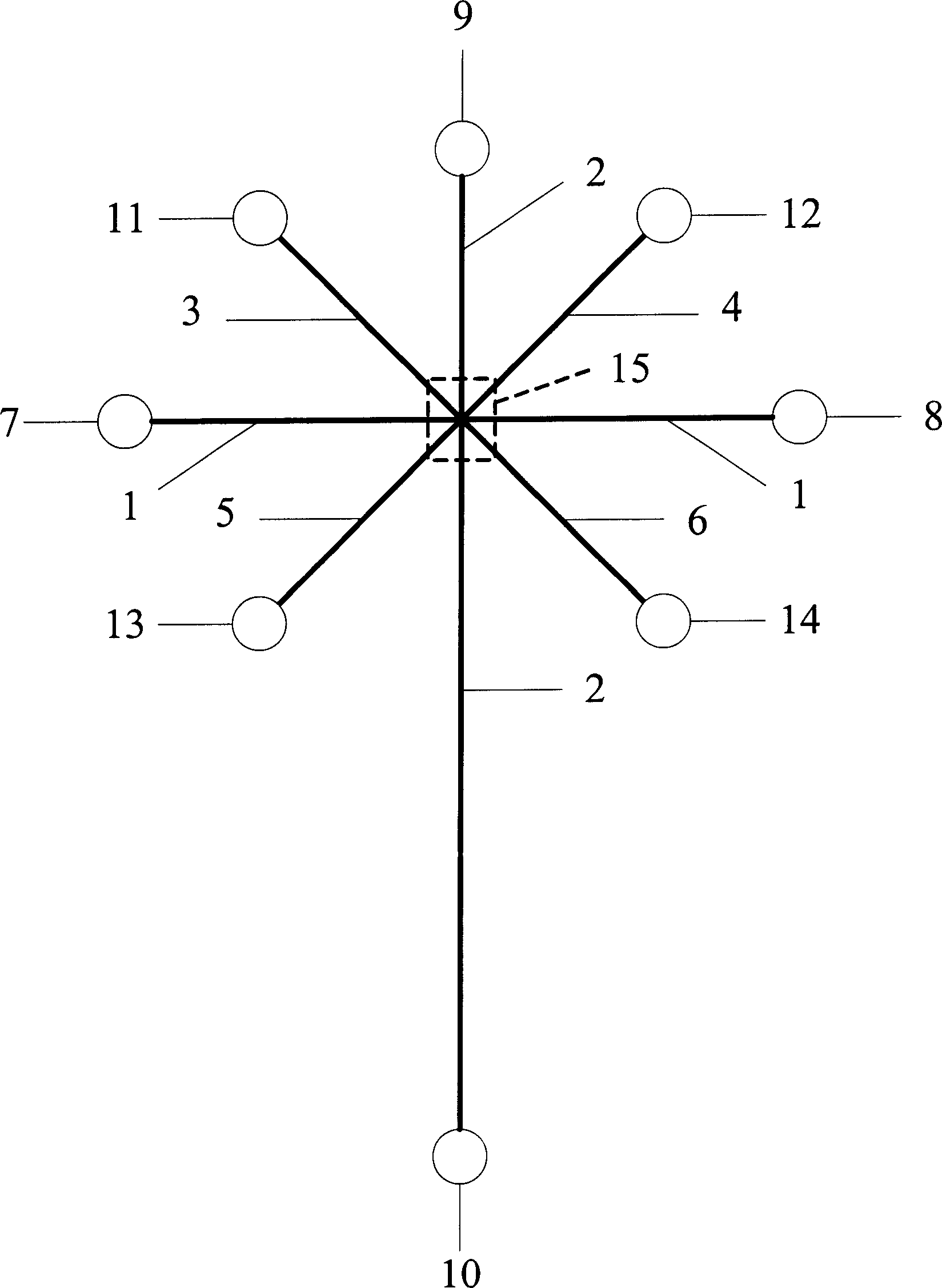
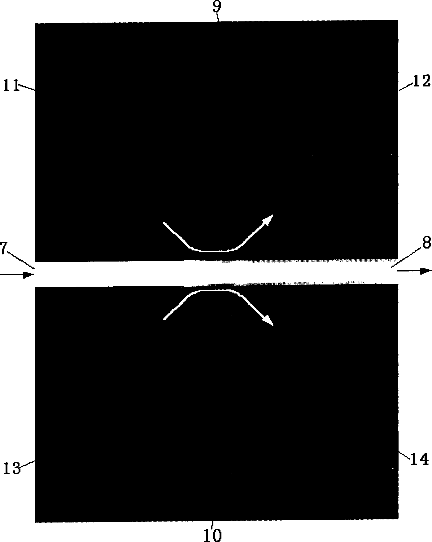
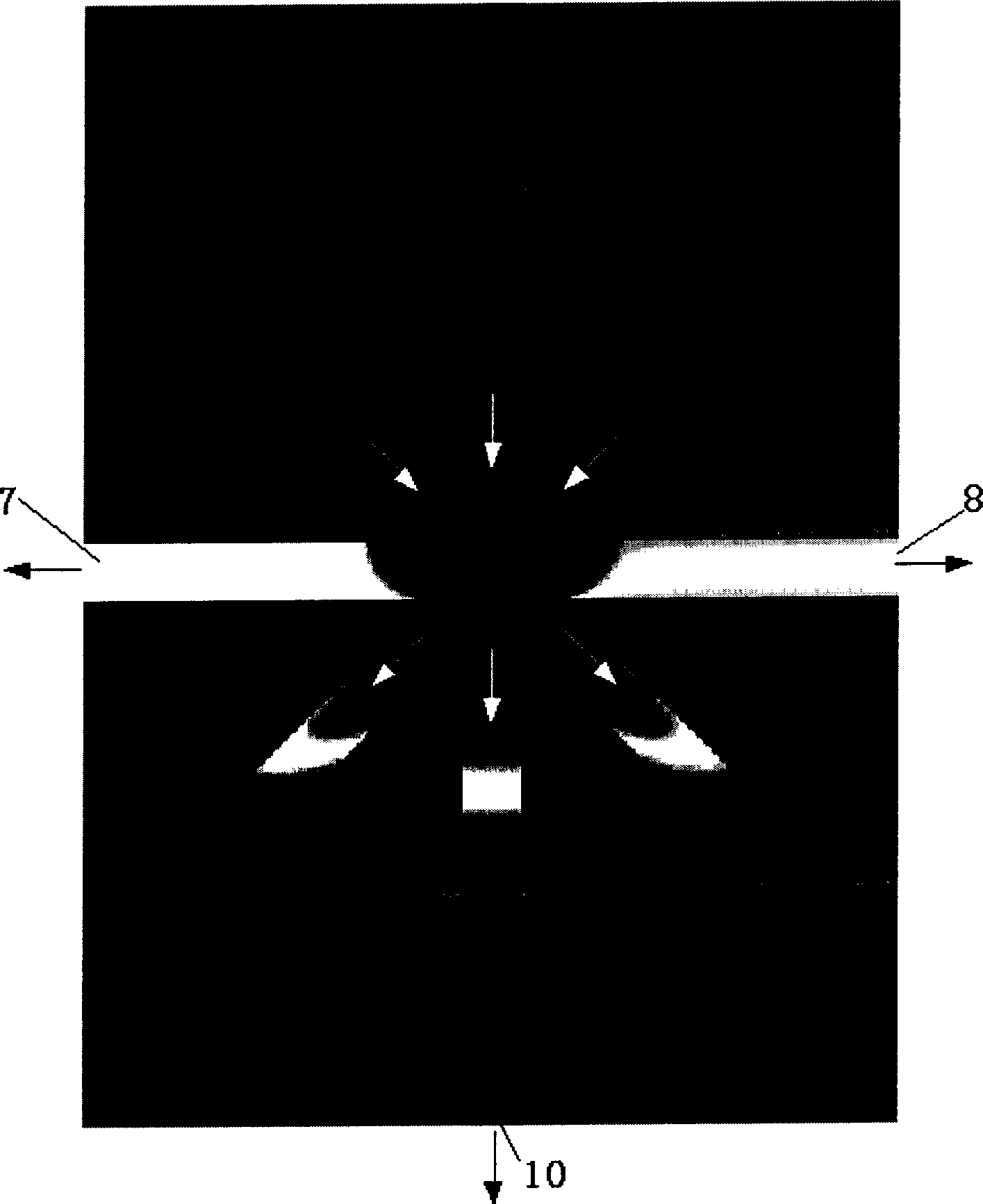
[0017] Such as figure 1 As shown, the capillary electrophoresis chip of the present invention with entrained flow sampling and its use method include a sampling channel 1 and a separation channel 2, the sampling channel 1 and the separation channel 2 are in vertical "cross" communication, and the sampling channel 1 The two ends are respectively connected with the sample liquid pool 7 and the waste liquid pool 8; the two ends of the separation channel 2 are respectively connected with the buffer pool 9 and the waste liquid pool 10, and also include four auxiliary entrainment channels, which are respectively the first auxiliary channel 3, the second auxiliary channel Two auxiliary channels 4, the third auxiliary channel 5 and the fourth auxiliary channel 6, the auxiliary entrainment channels are respectively located in the four regio...


PUM


Abstract

The entraining sampling capillary electrophoresis chip has auxiliary entraining tunnels on two sides of the sampling tunnel and the separating tunnel to form parallel entraining electric field to inhibit the dilatation of sample molecules in the intersection between the sampling tunnel and the separating tunnel and to raise the separating efficiency and detection sensitivity of the electrophoresis chip. In the same time, the chip can alter the width of sampling band via the entraining electric field strength relative to the sampling electric field, so as to regulate the sampling for fitting different analysis. The present invention may be used in the fast and sensitive separation and detection in inorganic molecule, organic molecule, macro biomolecule, virus, cell, etc.

Description

technical field [0001] The invention relates to a capillary electrophoresis chip in a clamping flow sampling mode and a use method thereof, and the chip can be applied to the fields of chemical and biological analysis and detection. Background technique [0002] The capillary electrophoresis chip technology developed rapidly after the 1990s is based on micro-machining technology, with silicon, glass, plastic (mainly plexiglass), ceramics and silicone rubber as the base material, and with the help of capillary electrophoresis technology, the sample is injected , reaction, separation, detection and other processes are integrated into a multi-functional, efficient and fast micro-laboratory technology. Because capillary electrophoresis chip has the characteristics of small size, high separation efficiency, few samples for analysis, fast analysis speed, and automatic analysis process, it has become the frontier and hot spot of international research. So far, capillary electropho...

Claims


Application Information

Patent Timeline
Patent Type & Authority Patents(China)
IPC IPC(8): G01N27/447B01D57/02
Inventor 李刚庄贵生冉瑞金庆辉赵建龙
Owner SHANGHAI INST OF MICROSYSTEM & INFORMATION TECH CHINESE ACAD OF SCI
Why Eureka
Try Eureka