Piston type liquid spraying device driven by marmen
The technology of memory alloy and liquid spraying device is applied in the directions of spraying device, liquid spraying device, mechanism generating mechanical power, etc. It can solve the problems of large investment of liquid spraying device, increase maintenance work, increase production cost, etc., and achieve simple maintenance work. Ease of operation, reduced maintenance costs, and cost-saving effects
- Summary
- Abstract
- Description
- Claims
- Application Information
AI Technical Summary
Problems solved by technology
Method used
Image
Examples
specific Embodiment approach 1
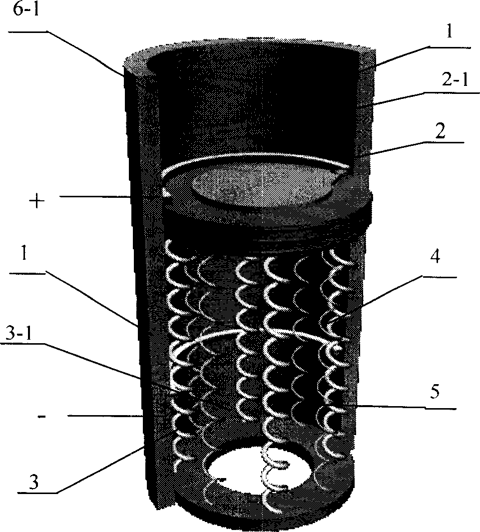
[0006] Specific implementation mode one: refer to figure 1 , the piston-type liquid spraying device driven by the shape memory alloy driver of the present embodiment includes a liquid cylinder 1, a piston 2 that can move up and down is provided in the liquid cylinder 1, and a one-way valve 2-1 is provided on the piston 2. The liquid cylinder The lower bottom of 1 is provided with an annular bottom plate 3, and a driver 4 made of a shape memory alloy material is fixedly connected between the bottom plate 3 and the piston 2, and the shape of the driver 4 is a coil spring or a rod.
[0007] Some alloys restore the high-temperature phase shape when heated, and can restore the low-temperature phase shape when cooled, which is called a two-way memory effect alloy. When the present invention uses the two-way memory effect alloy, there is no need to install a return spring. The shape memory alloy driver 4 is energized to reach the reverse phase transition point to generate expansion ...
specific Embodiment approach 2
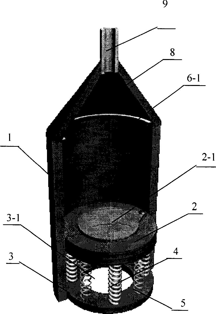
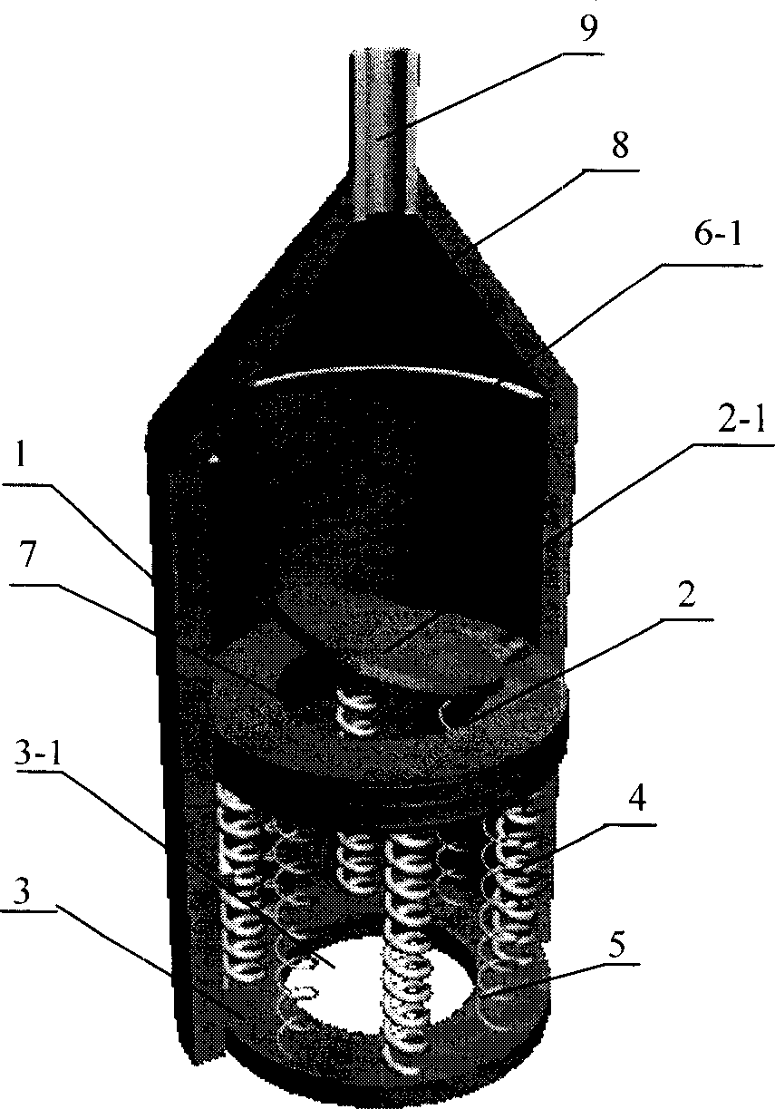
[0009] Specific embodiment two: This embodiment is used as a fountain driven by a one-way shape memory alloy, refer to Figure 4 , The hydraulic cylinder is installed on the steering device through the bracket. The inside of the liquid cylinder 1 communicates with the water in the pool through the bottom plate 3 with the hole 3-1 in the middle, refer to figure 2 , image 3 , The upper part of the cylinder is equipped with a compression container 8 and a nozzle 9. The whole device is submerged in water, and the uppermost end of the nozzle is close to the water surface.
[0010] The driver 4 used in this embodiment is made of a shape memory alloy with one-way memory effect, and the shape of the driver 4 is a helical spring. Refer to figure 2 , image 3 , The number of helical spring-shaped shape memory alloy drivers is four, and they are connected in series in the circuit to ensure that the reverse phase transition point is reached at the same time when electrified, so tha...
specific Embodiment approach 3
[0013] Specific implementation mode three: the difference between this implementation mode and specific implementation mode two is that, refer to Figure 5 , Figure 6 , the shape of the driver 4 is a rod.
PUM
 Abstract
Description
Claims
Application Information
 - R&D
- Intellectual Property
- Life Sciences
- Materials
- Tech Scout
- Unparalleled Data Quality
- Higher Quality Content
- 60% Fewer Hallucinations
Browse by: Latest US Patents, China's latest patents, Technical Efficacy Thesaurus, Application Domain, Technology Topic, Popular Technical Reports.
© 2025 PatSnap. All rights reserved.Legal|Privacy policy|Modern Slavery Act Transparency Statement|Sitemap|About US| Contact US: help@patsnap.com


