Eureka AIR delivers breakthrough ideas for toughest innovation challenges, trusted by R&D personnel around the world.

Optical module and method for manufacturing same

An optical module and molding technology, applied in the field of optical modules, can solve problems such as low production efficiency, high price, and modules not suitable for mass production

Inactive Publication Date: 2006-01-11
TDK CORPARATION
View PDF0 Cites 6 Cited by
  • Summary
  • Abstract
  • Description
  • Claims
  • Application Information

AI Technical Summary

Problems solved by technology

[0006] However, due to Figure 26 Optical modules 10 of the type shown require a high degree of precision in the positioning of each individual component therein and, in some cases, precise adjustments by skilled labor.
Therefore, the problem of this kind of optical module is that the production efficiency is low, which makes this kind of module unsuitable for mass production
However, the problem with this optical module is that it is very expensive and requires high connection accuracy between the optical fiber and the optical waveguide

Method used


Image

  • Optical module and method for manufacturing same
  • Optical module and method for manufacturing same
  • Optical module and method for manufacturing same

Examples


Embodiment Construction

[0056] Preferred embodiments of the present invention will be described in detail below with reference to the accompanying drawings.

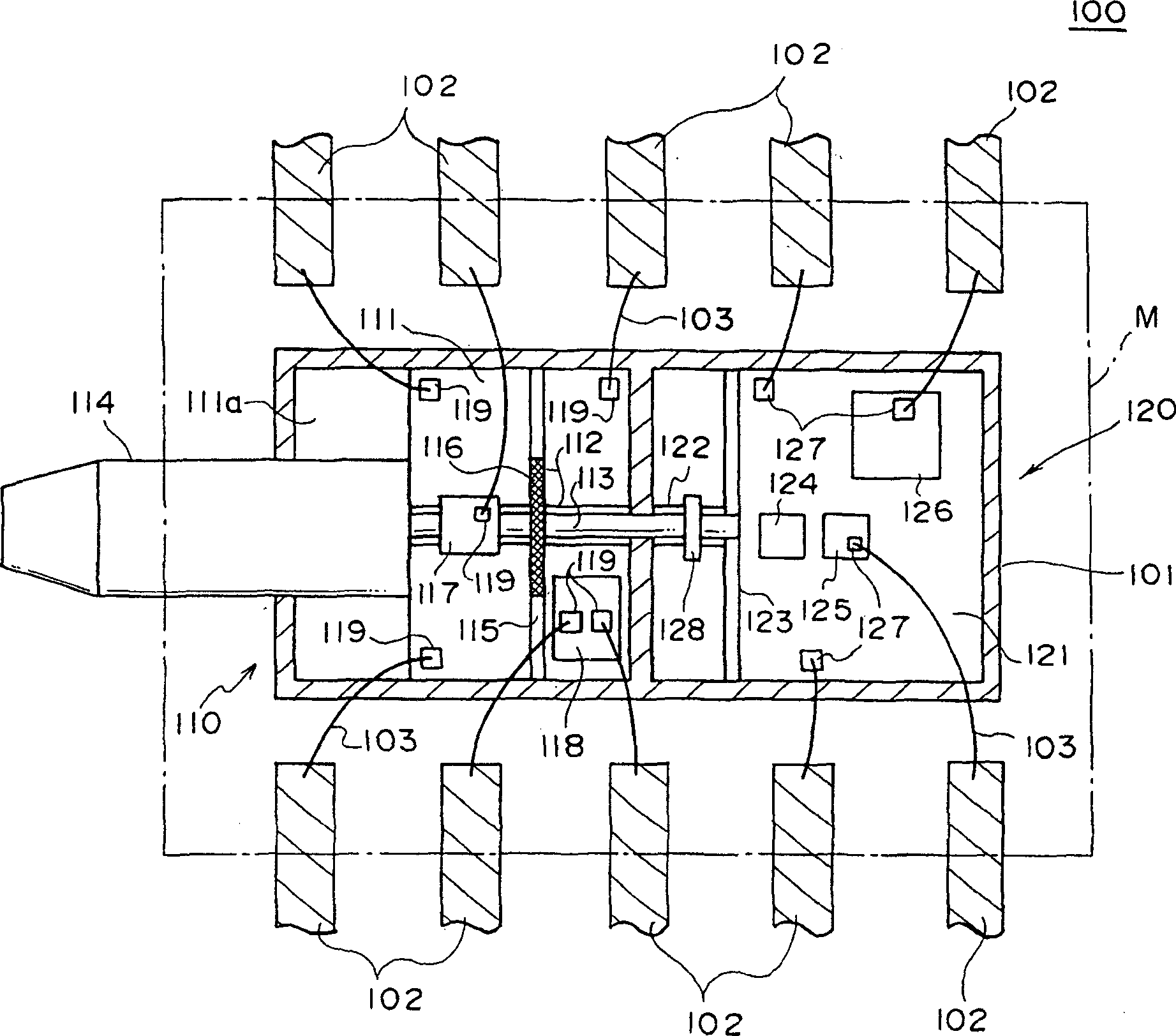
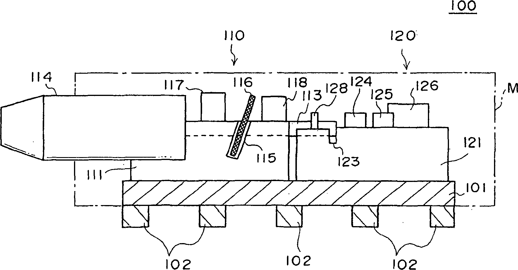
[0057] figure 1 It is a plan view of the structure of the main part of the optical module 100 described in a preferred embodiment of the present invention, figure 2 It is a side view of the structure of the main part of the optical module 100. Although, as will be described below, the optical module 100 described in this embodiment will be finally packaged, and its main part will be covered by resin, figure 1 Shown is the optical module 100 without resin encapsulation. figure 1 and figure 2 The area indicated by M in is the area that will be finally packaged.

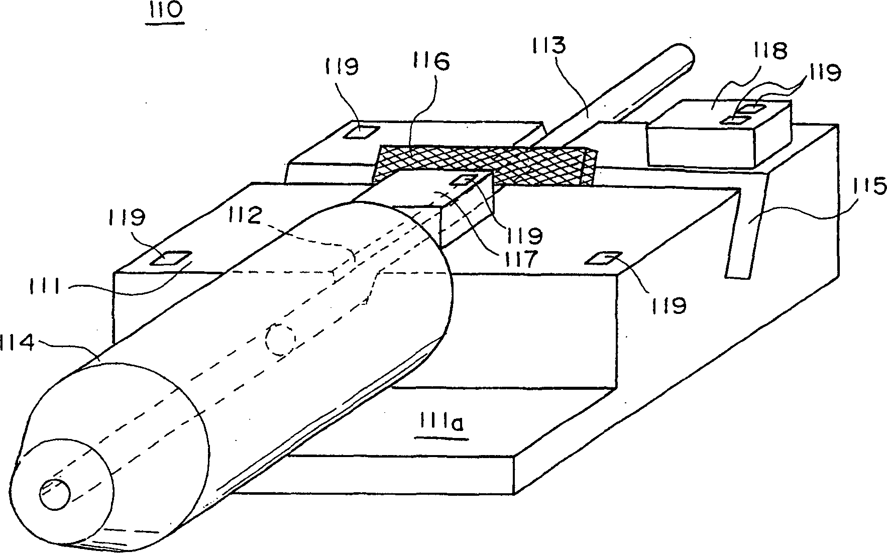
[0058] Such as figure 1 and 2 As shown, the optical module 100 according to this embodiment includes: a molding pad 101 , a plurality of leads 102 , a first platform 110 and a second platform 120 mounted on the molding pad 101 .

[0059] The die pads 101 and leads 102 are pa...


PUM


Abstract

An optical module which can be manufactured by a simple process at low cost is disclosed. A method for manufacturing such an optical module is also disclosed. An optical module (100) comprises a die pad (101), a plurality of leads (102), and a first platform (110) and a second platform (120) mounted on the die pad (101). At least an optical fiber (113) is fixed to the main body (111) of the first platform (110), and at least a light emitter (124) is mounted on the main body (121) of the second platform (120). The light emitter (124) generates an optical signal to be transmitted through the optical fiber (113).

Description

technical field [0001] The invention relates to an optical module and a method for manufacturing the optical module, in particular to an optical module with simple manufacturing process and low cost and a method for manufacturing the optical module. Background technique [0002] The emergence of the Internet enables users to access and process a large amount of information in real time. While information can be sent and received using copper wires, fiber optics, wireless, and similar transmission methods, fiber optics are more advantageous at transmitting large amounts of information at high rates. Therefore, it can be predicted that in the future, optical fiber will be extended to every family to realize fiber-to-the-home. [0003] However, since the signals used by the terminal equipment when processing information are electrical signals rather than optical signals, when the terminal equipment is connected through an optical fiber, a so-called optical module needs to be p...

Claims


Application Information

Patent Timeline
Patent Type & Authority Applications(China)
IPC IPC(8): G02B6/42H01S5/022H01S5/0232H01S5/0683
CPCH01S5/02216H01S5/0683G02B6/4207G02B6/4201H01S5/005H01S5/02284G02B6/4292H01S5/02252G02B6/421H01L2924/181H01L2224/48091H01L2224/48247G02B6/4243G02B6/4253G02B6/4255H01S5/0231H01S5/02326H01S5/02251H01S5/0232H01L2924/00012H01L2924/00014
Inventor 罗永辉秦健次郎木练透花岛直树
Owner TDK CORPARATION
Why Eureka
Eureka Blog
Learn More