Metal melting furnace

A melting furnace and melting technology, applied in furnaces, furnace components, metallurgical equipment, etc., can solve problems such as difficult to completely remove impurities, reduced retention of molten liquid, and difficult operations

Active Publication Date: 2006-01-25
MEICHU
View PDF0 Cites 3 Cited by
  • Summary
  • Abstract
  • Description
  • Claims
  • Application Information

AI Technical Summary

Problems solved by technology

[0007] The impurity treatment by flux is usually carried out once every 8 hours, but due to the difficulty of operation, it is difficult to completely remove the impurities, and a part of them flows to the suction part 140, resulting in a decrease in the quality of the molten liquid, and heavy metal oxides settle in the molten liquid. The furnace bottom of the part 135 is piled up, which will cause the amount of molten liquid held in the molten liquid holding part 135 to decrease.

Method used


Image

  • Metal melting furnace
  • Metal melting furnace
  • Metal melting furnace

Examples


Embodiment Construction

[0024] The present invention will be described in detail below with reference to the accompanying drawings.

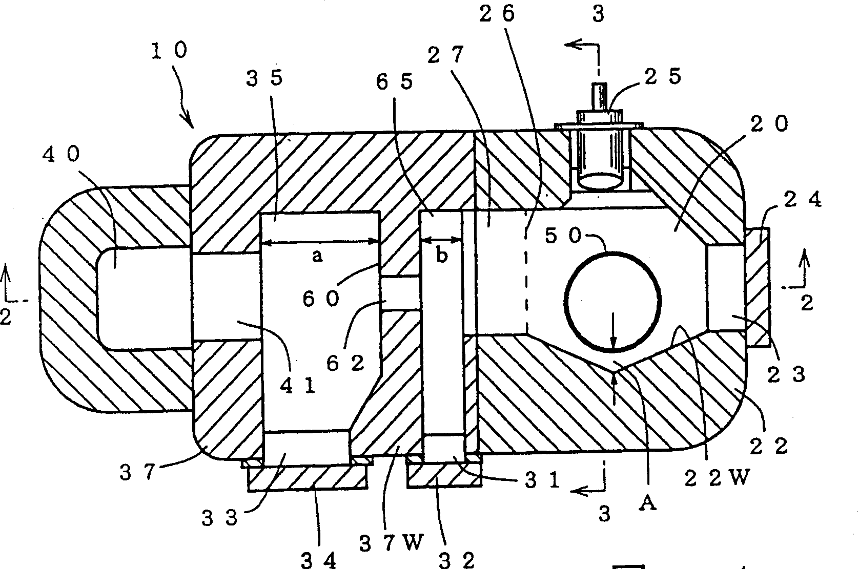
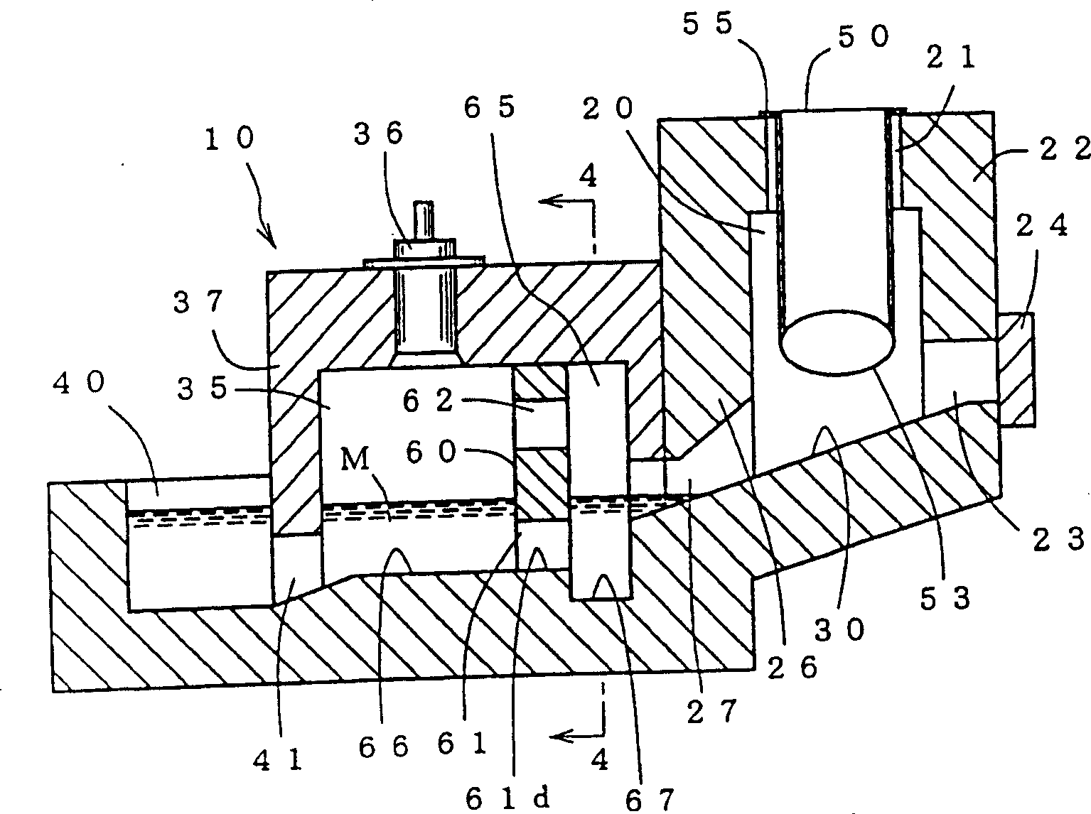
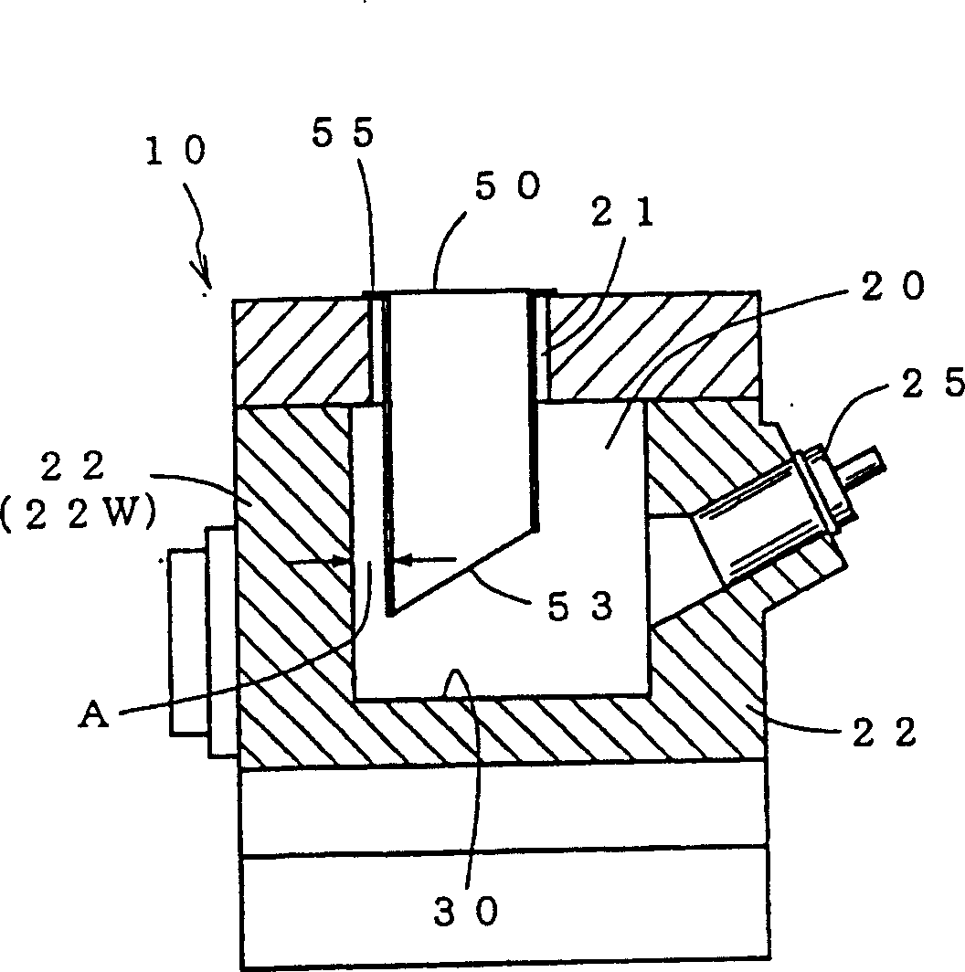
[0025] figure 1 is an overall schematic cross-sectional view of a metal melting furnace showing an embodiment of the present invention, figure 2 is along figure 1 The cross-sectional view of the 2-2 line cut, image 3 is along figure 1 The enlarged cross-sectional view of the 3-3 line cut, Figure 4 is along figure 2 Sectional drawing of the 4-4 line cut.

[0026] The metal melting furnace 10 in the embodiment is a so-called hand melting furnace that melts and holds molten aluminum for aluminum casting, such as Figure 1 to Figure 4 As shown, after the molten material is inserted into the preheating flue 20 formed as a material inlet (and exhaust port) 21 at the upper part and has an inclined furnace bottom 30 at the lower part, the melting burner arranged toward the aforementioned preheating flue 20 is used to 25. The molten material is heated and melted, ...


PUM

PropertyMeasurementUnit
thicknessaaaaaaaaaa

Abstract

In a metal melting furnace, a separation wall 60 is provided between an inclined hearth 30 and a molten metal reservoir 35 to define a molten metal processing portion 65 . The separation wall is provided with a connecting passage 61 for the molten metal, between the molten metal reservoir and the molten metal processing portion, at a height level higher than a bottom surface 67 of the molten metal processing portion. The separation wall is also provided on its upper portion with an exhaust gas passage which permits exhaust gas discharged from the molten metal reservoir to pass therethrough. An inspection opening 31 with a door 32 is provided in a furnace wall surface 37 W to open into the molten metal processing portion.

Description

technical field [0001] The present invention relates to metal melting furnaces such as aluminum. Background technique [0002] The inventors have previously proposed Figure 5 to Figure 7 The metal melting furnace 100. This kind of melting furnace is formed as a material inlet 121 at the top and a preheating flue 120 with an inclined furnace bottom 130 is inserted into the molten material, and then the melting burner 125 arranged toward the lower part of the preheating flue 120 is used to burn the aforementioned The molten material is heated and melted, and introduced into the molten liquid holding part 135 through the aforementioned inclined furnace bottom 130, and the molten liquid M is kept at a predetermined temperature by a holding burner 136 in the molten liquid holding part 135. Inside, there is a gap C between the molten material holding member 150 whose lower portion is open and the furnace wall surface 122W on the side opposite to the melting burner 125 of the flu...

Claims


Application Information

Patent Timeline
Patent Type & Authority Applications(China)
IPC IPC(8): F27B3/04C21C5/56C22B21/00C22B21/06F27B3/18F27B3/20F27D3/10F27D13/00
CPCC22B21/06C21C5/567F27B3/205Y10S266/90F27B3/18C22B21/0084F27B3/04
Inventor 中岛光谦
Owner MEICHU
Why Eureka
Try Eureka