Antitheft device

An anti-theft device and detection device technology, which is applied to control devices, anti-theft alarms, and anti-theft alarm mechanical start-ups, can solve the problems of increased communication times and high communication costs, and achieve the goals of suppressing communication times, reducing communication costs, and prolonging time Effect

Inactive Publication Date: 2006-01-25
HITACHI CONSTRUCTION MACHINERY CO LTD
View PDF1 Cites 5 Cited by
  • Summary
  • Abstract
  • Description
  • Claims
  • Application Information

AI Technical Summary

Problems solved by technology

The aforementioned prior art does not specifically mention the situation when the engine is stopped, but it is configured to continuously supply power to a control device that detects the position at all times and transmits and receives signals to and from the management server, for example, including when the engine is stopped. In the case of the power supply installed on the hydraulic excavator, that is, the voltage of the battery drops in a short period of time (so-called battery exhaustion), and it is necessary to perform frequent charging operations.
In addition, there is also the following problem: as in the above-mentioned prior art, the location information of the hydraulic excavator needs to be sent to the management server side, and when the management server side judges whether it is out of the normal operation range, the relationship between the hydraulic excavator and the management server The number of communications increases, and the communication cost is relatively high

Method used


Image

  • Antitheft device
  • Antitheft device
  • Antitheft device

Examples


Embodiment Construction

[0024] Next, embodiments of the present invention will be described with reference to the drawings.

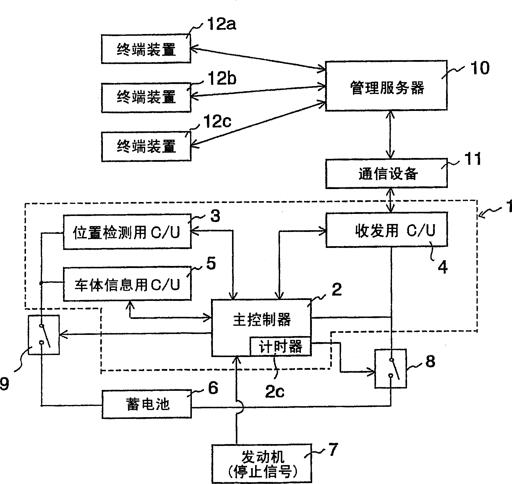
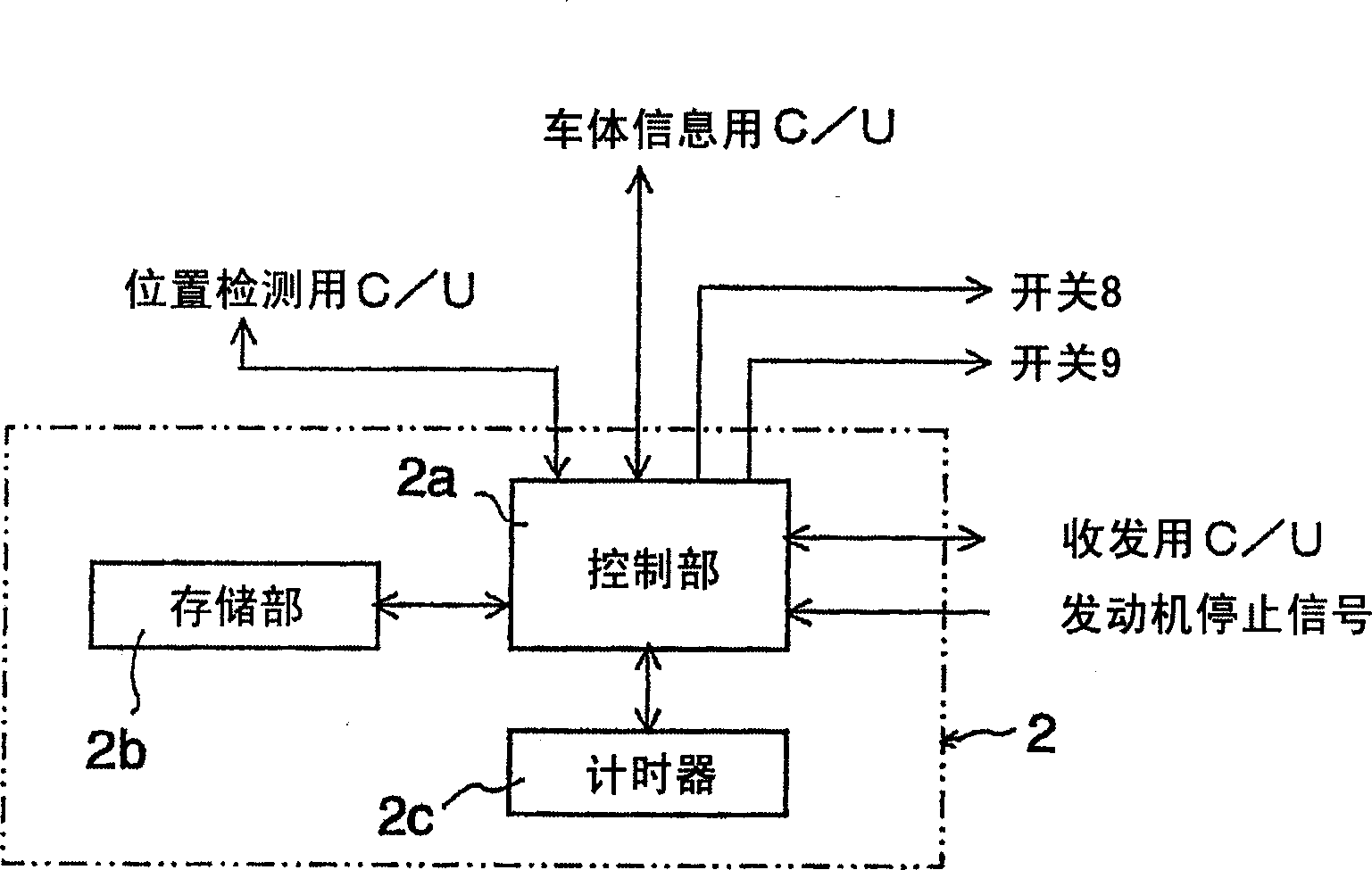
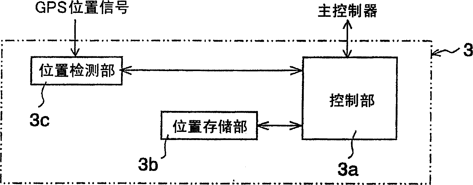
[0025] Figure 1 to Figure 8 is a diagram for explaining the first embodiment of the present invention, figure 1 It is the overall structure diagram of the anti-theft device of the first embodiment; figure 2 is formed figure 1 The main controller block diagram of the anti-theft device is shown in ; image 3 is the block diagram of the control unit for position detection; Figure 4 is the block diagram of the control unit for vehicle body information; Figure 5 It is a flow chart of calculation processing after the first predetermined time T s has passed after the engine stop signal is input; Fig. 6 is a flow chart of calculation processing after the first predetermined time T s has passed; Figure 7 It is the processing flow when the information request signal is input from the management server; Figure 8 It is a time chart after inputting an engine stop signal.

[00...


PUM


Abstract

The present invention provides an anitheft device constructed such that when a stop signal is input from an engine (7), a main controller (2) outputs, until a first specified time Ts elapses, a connection signal to switches (8, 9) to execute an antitheft processing in the same manner as when the engine (7) is operated, instructs to the switch (9), after an elapse of the first specified time Ts, to repeat a connection and a disconnection at every specified time interval Deltat, and detects by a position detecting controller (3) a position at an instruction every time a connection is made to determined the possibility of a theft by comparing that position with a position at the engine stop, whereby it becomes unnecessary to always supply power to the controller (3) during the engine (7) stop to be able to save as much power supply to the controller (3) as time elapsed during which the switch (9) is disconnected and minimize the power consumption of a control device at the engine stop time.

Description

technical field [0001] The present invention relates to an anti-theft device installed on a self-propelled mobile body including a construction machine such as a hydraulic excavator and grasped by a management server at a place away from the mobile body. Background technique [0002] As this anti-theft device, for example, on JP-A-2000-73411, it is disclosed that, for example, the position of the self-propelled mobile body of the management object is detected by the Global Positioning System (GPS), and the detected position is transmitted by wireless communication. The technology of sending the position of the hydraulic excavator to the management server in a remote place, and confirming whether the position of the hydraulic excavator is within the predetermined normal operation range through the management server. [0003] In this prior art, when the position of the hydraulic shovel detected by GPS is judged to be out of the normal operation range, an engine stop signal is ...

Claims


Application Information

Patent Timeline
Patent Type & Authority Applications(China)
IPC IPC(8): B60R25/10B60R25/04G08B13/00E02F9/24B60R25/102B60R25/33B60R25/40G08B13/14G08G1/123
CPCB60R25/102B60R25/04G08G1/205G08B13/1409B60W2550/402B60R25/33B60W2556/50B60R25/045B60R16/03
Inventor 小松英树杉山玄六足立宏之柴森一浩柴田浩一
Owner HITACHI CONSTRUCTION MACHINERY CO LTD
Why Eureka
Try Eureka