
Shaping method of thick light guiding plate and its mould

A molding method and technology for light guide plates, which are used in home appliances, other home appliances, applications, etc., can solve the problems of shrinking concave spots of thick light guide plates and reducing the quality of light guide plates, and achieve suppression of surface shrinkage concave spots, excellent reproducibility, The effect of shortened molding cycle

Inactive Publication Date: 2006-02-01
JAPAN STEEL WORKS LTD +2
View PDF7 Cites 17 Cited by
  • Summary
  • Abstract
  • Description
  • Claims
  • Application Information

AI Technical Summary

Problems solved by technology

However, sometimes depressions, shrinkage pits or dents are formed on the surface of a thick light guide plate, and the quality of the light guide plate is significantly reduced.

Method used


Image

  • Shaping method of thick light guiding plate and its mould
  • Shaping method of thick light guiding plate and its mould
  • Shaping method of thick light guiding plate and its mould

Examples


Embodiment 1

[0062] Embodiment 1: Keep the peripheral wall insert and the mold core insert at a constant temperature of 90°C, and only heat and cool the mold cavity insert between 85°C and 40°C for compression molding. The molding cycle was shortened to 260 seconds, but its quality was poor in terms of shrinkage pitting, reproducibility, and warpage.

Embodiment 2

[0063] Example 2: Raise the surrounding wall insert to 110°C, heat and cool the mold cavity insert between 104°C and 45°C, heat and cool the mold core insert between 83°C and 38°C, and perform compression molding .

[0064] The molding cycle was shortened to 200 seconds, and the shrinkage pit was slightly inferior, but good results were obtained in terms of reproducibility and warpage.

Embodiment 3

[0065] Example 3: heating and cooling the surrounding wall inserts between 130°C and 35°C, heating and cooling the mold cavity inserts between 110°C and 35°C, forming an insulating layer on the surface of the core inserts and cooling to 35°C for compression molding.

[0066] When compression molding was performed by heating and cooling with the temperature of the peripheral wall insert higher than that of the cavity insert, the molding cycle was shortened to 175 seconds, and the quality of shrinkage pitting, reproducibility, and warpage was improved.


PUM


Abstract

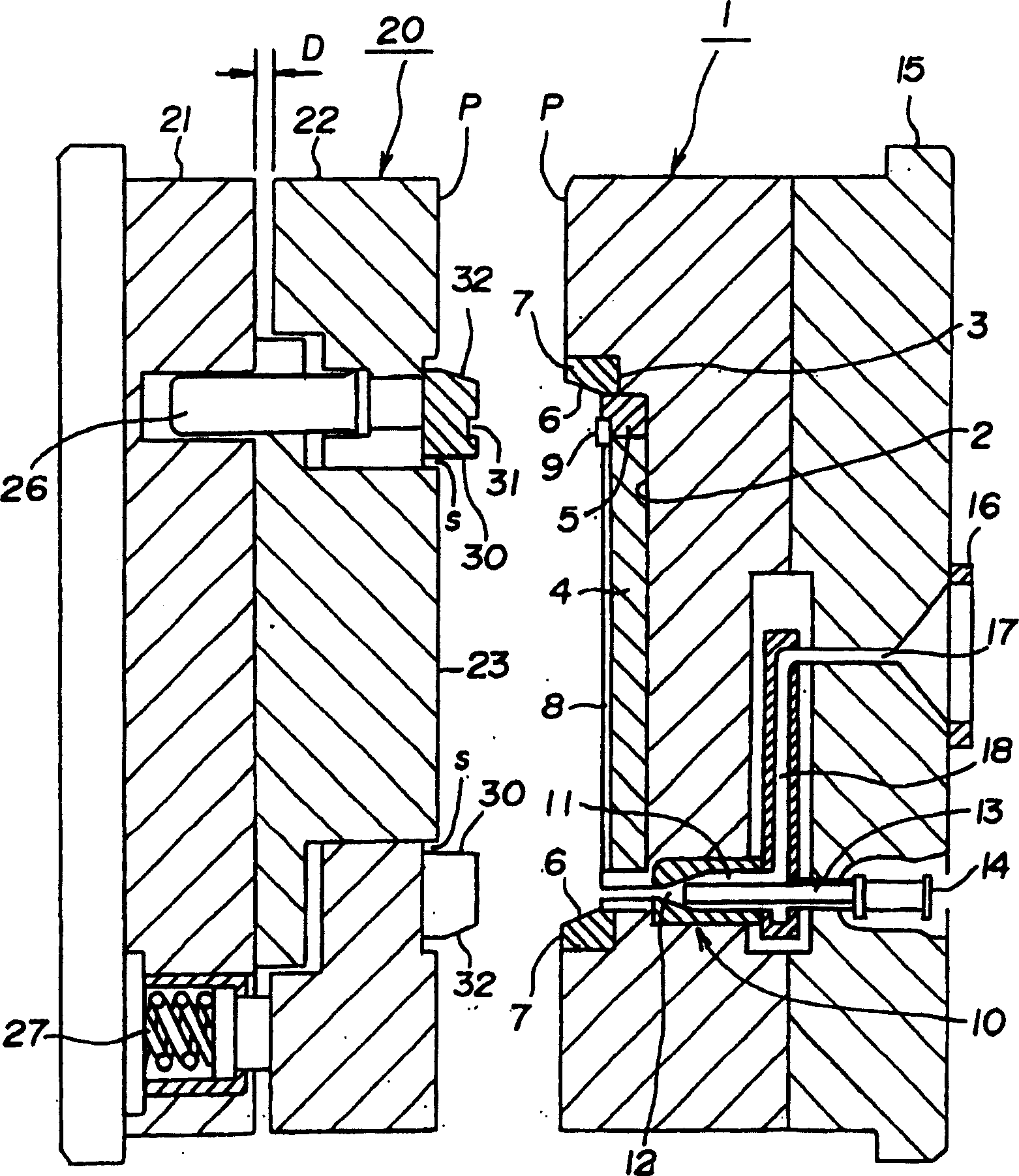
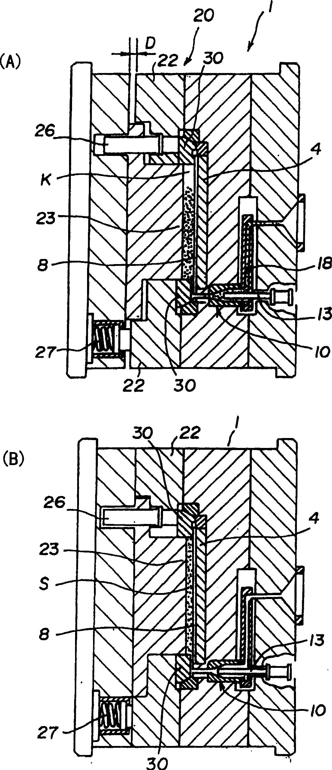
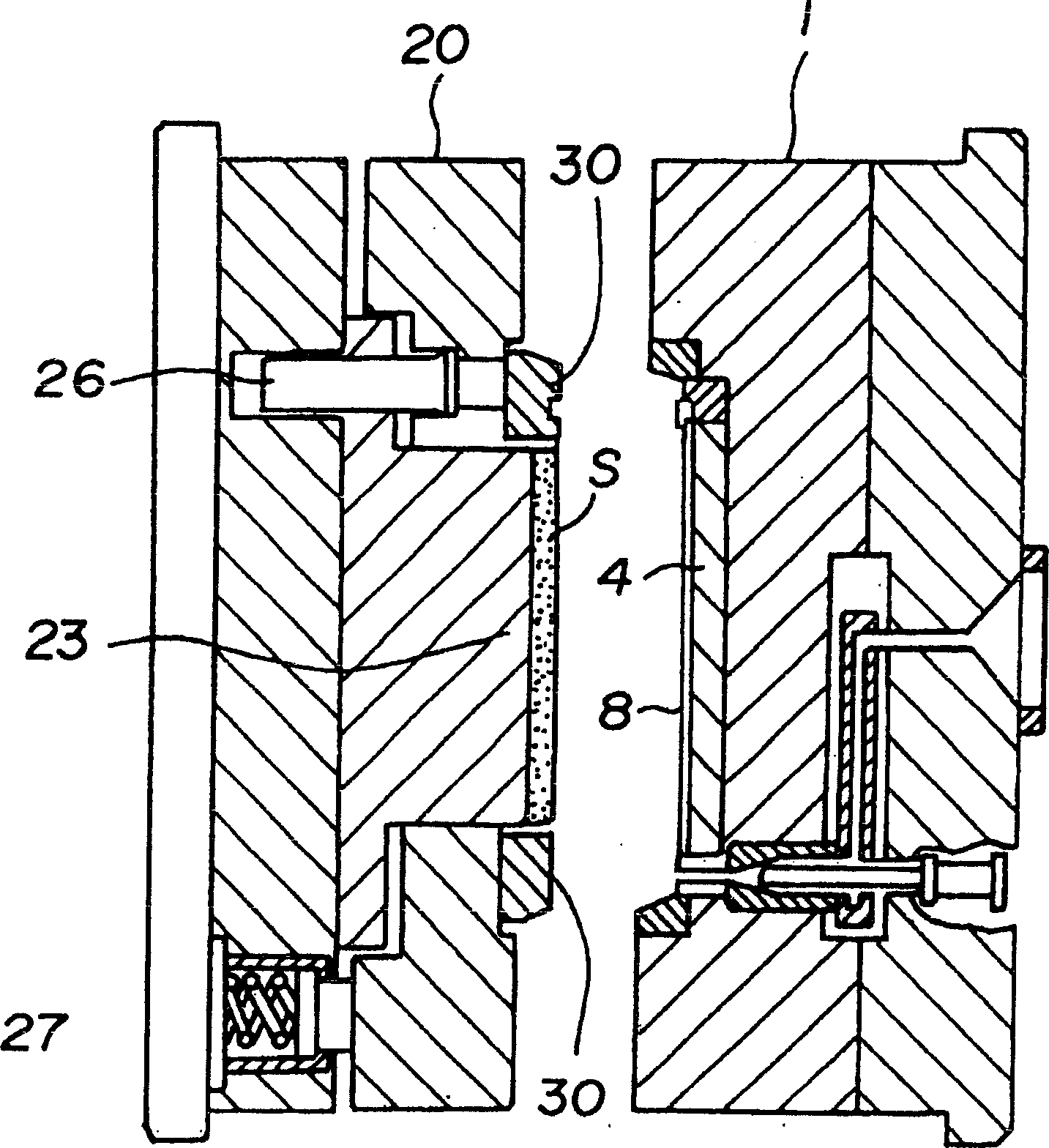
The present invention provides a molding method capable of molding a thick-walled light guide plate of high quality by a short molding cycle. A predetermined amount of a molten resin is charged in the shaping space K constituted of the stamper (8) provided to the core (4) on the cavity side of a fixed mold, the core 23 on the core side of a movable mold and cores 30 and 30 on the peripheral wall side of the movable mold. Then, a valve gate is closed to compress the molten resin by the core 23 on the core side. Transfer properties are enhanced by compression and the molding cycle is shortened. At the time of compression, the temperature of the cores (30 and 30) on the peripheral wall side is made higher than the temperature of the core (4) on the cavity side and the core (23) on the core side. By this constitution, the cooling speed of the cores (30 and 30) on the peripheral wall side becomes slow to enhance a compression effect and the occurrence of a sink is suppressed.

Description

technical field [0001] The present invention relates to a molding method and mold for a light guide plate made of synthetic resin used as a backlight of a liquid crystal display. Although not limited thereto, it relates to a molding method and molding suitable for molding a large thick light guide plate with a thickness of 6 mm or more, for example. With mold. Background technique [0002] Liquid crystal display devices such as computers and liquid crystal televisions are composed of a liquid crystal display and a light guide plate. In addition, a light source is provided on the side of the light guide plate. Therefore, the light emitted from the light source is reflected by the reflective layer formed on one surface of the light guide plate, and is emitted from the light emitting surface. The entire surface of the liquid crystal display is illuminated by this light. [0003] This kind of light guide plate is made by cutting an acrylic resin plate into a predetermined siz...

Claims


Application Information

Patent Timeline
IPC IPC(8): B29C45/78B29C45/56B29C45/57B29C45/37B29C45/73B29C45/17B29C45/26B29L11/00G02B6/00B29C45/70G02B5/00
CPCB29C45/46B29C45/70B29C45/73B29C45/7331B29C2045/7393G02B5/0268
Inventor 横山和久中岛英昭沖∴次矶部文敏武内敦中川隆
Owner JAPAN STEEL WORKS LTD
Learn More