Method of wind electric power generation

A technology of wind power generators and generators, applied in wind power generation, wind power engines, wind power motor combinations, etc., can solve problems such as unstable wind direction and windy time, difficulty in finding a fixed location, hidden safety hazards, etc., to reduce implementation costs , Simplify equipment, reduce the effect of requirements

Inactive Publication Date: 2006-02-01
连伟 +1
View PDF0 Cites 7 Cited by
  • Summary
  • Abstract
  • Description
  • Claims
  • Application Information

AI Technical Summary

Problems solved by technology

[0004] In the process of comprehensive consideration of man-made buildings and energy development, someone once proposed to use the local strong wind generated by the "narrow tube effect" between tall buildings to generate electricity. Unfortunately, in this idea, 1. The generator needs to be installed on both sides It is difficult to find a suitable fixed position between two high-rise buildings. Even if it is fixed, it will bring hidden dangers in safety and affect the city appearance; 2. Although the instantaneous wind strength between high-rise buildings is strong, the wind direction and wind time are unstable. Requires expensive controls to keep the generators oriented correctly; thus never really implemented in the end

Method used


Image

  • Method of wind electric power generation
  • Method of wind electric power generation
  • Method of wind electric power generation

Examples


Embodiment 1

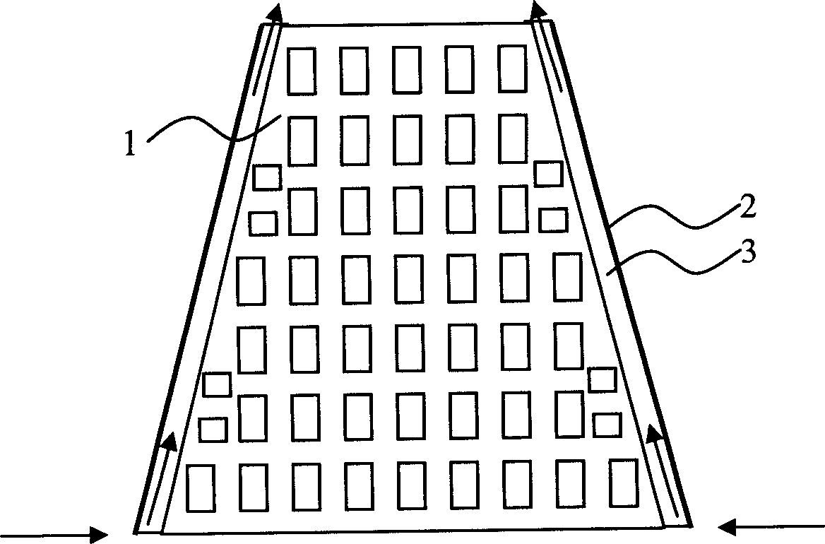
[0032] Embodiment 1. The channel is formed by a part of the structure of the building, and the part of the structure is original to the building.

[0033] combine figure 1 , the high-rise building 1 has a trapezoidal cross-section with a small top and a large bottom, and its side is covered by a glass curtain wall 2 . There is a gap between the glass curtain wall 2 and the wall of the high-rise building 1 to form a channel 3 . The updraft that gathers from the surface along the figure 1 The direction of the middle arrow gradually accelerates to the top of the high-rise building 1 through the channel 3, and after the convergence of the air duct arranged at the air outlet, the wind power generator installed on the top of the high-rise building 1 is pushed to generate electric energy (the air duct and the generator are not shown in the figure. draw).

Embodiment 2

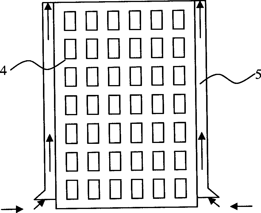
[0034] Embodiment 2, the channel is formed by a part of the structure of the building, and this part of the structure is attached to the original building.

[0035] combine figure 2 , the building 4 has a consistent cuboid structure up and down, and a vertical hollow pipe 5 is respectively built along the walls at its four corners, and the inside of the pipe 5 is a passage. The updraft that gathers from the surface along the figure 2 The top of the building 4 that the direction of the middle arrow reaches through the pipeline 5 pushes the wind power generator installed on the top of the building 4 to send electric energy after the convergence of the air duct arranged at the air outlet (the air duct and the generator are not drawn in the figure ).

Embodiment 3

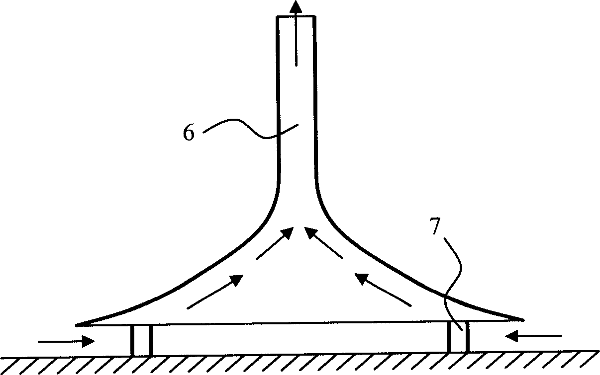
[0036] Embodiment 3, the channel is formed by the whole of a special building.

[0037] combine image 3 , the special building 6 is in the shape of an inverted trumpet, and the interior is hollow to form a channel. There is a gap between the bell mouth and the ground, which is supported on the ground by pillars 7. The wall, that is, the wall of the channel, adopts a metal frame and the surface is covered with a film structure. The updraft that gathers from the surface along the image 3 The direction of the middle arrow reaches the top of the special building 6, and promotes the wind power generator installed on the top of the special building 6 after converging at the air duct provided at the air-flow outlet to send electric energy (the air duct and the generator are not drawn in the figure).

[0038] The special building in this example adopts a frame-covered structure, which is light in weight, easy to build and move, and can be set in areas with a certain open area such as...


PUM


Abstract

The present invention discloses a wind power generation method. It utilizes upward rising air flow in the vertical channel, and utilizes wind-driven power generator mounted in the air flow outlet to make air flow drive generator to generate electric energy. The described channel can be formed by partial building or whole building.

Description

【Technical field】 [0001] The invention relates to the development of clean and environment-friendly energy, in particular to a wind power generation method. 【Background technique】 [0002] With the continuous acceleration of social industrialization and urbanization, the energy crisis has become an unavoidable problem. People urgently need to find various clean and economical renewable energy sources to replace those increasingly depleted non-renewable resources, including oil, natural gas, coal, etc. At present, the widely researched and applied renewable energies mainly include water energy, solar energy, wind energy, etc., and the utilization of these energies mainly depends on their natural existence in nature. For example, a hydropower station should be built in a narrow area with sharp water drops, a solar installation should be installed in an area with sufficient sunshine all year round, and a wind power plant should be built on a flat and wide plateau. With the co...

Claims


Application Information

Patent Timeline
Patent Type & Authority Applications(China)
IPC IPC(8): F03D1/04F03D9/00F03D7/04F21S9/02F03D9/25F03D9/35F03D9/45
CPCY02E10/723Y02E10/725Y02B10/30Y02E10/72
Inventor 吕大明连伟
Owner 连伟
Why Eureka
Try Eureka