Deployable structure

A technology for components and rigid components, applied in the field of deployable structures, which can solve problems such as limitations

Inactive Publication Date: 2006-02-01
ISIS INNOVATION LTD
View PDF0 Cites 33 Cited by
  • Summary
  • Abstract
  • Description
  • Claims
  • Application Information

AI Technical Summary

Problems solved by technology

Therefore, the deployment configuration is limited by the design of the structural mechanism itself

Method used


Image

  • Deployable structure
  • Deployable structure
  • Deployable structure

Examples


Embodiment Construction

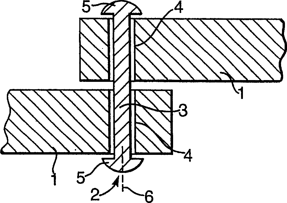
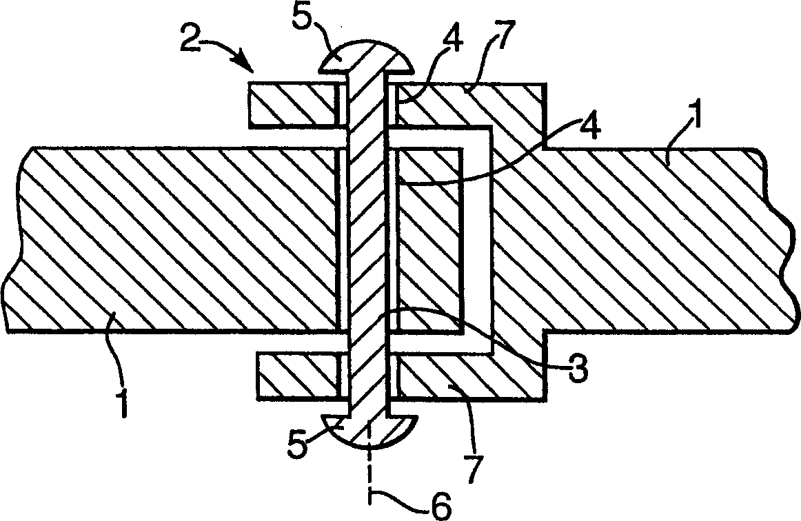
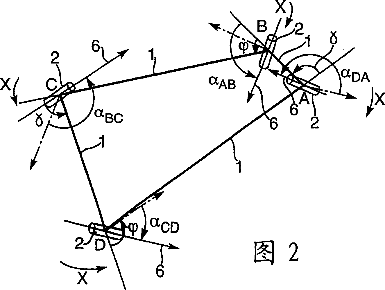
[0041] The deployable mechanism comprises a structural mechanism consisting of a plurality of rigid members 1 which are connected by rotating joints 2 (for example, respectively at Figure 1A and Figure 1B Alternative connectors 2) shown in sectional view of .

[0042]Rigid member 1 may have any structural form. "Rigid" means that the member is rigid enough to maintain a single degree of movement of the structural mechanism. In practice, in any particular application, the member 1 will inevitably have some degree of flexibility. Member 1 may be a simple cylindrical rod as shown in FIG. 1 . However, the members may have any cross-section. In the construction mechanism described below, the elements 1 are straight, but in principle they could be equally curved.

[0043] The link 2 connecting the components 1 allows relative rotation of the two components 1 connected by the link 2 about the axis of rotation 6 . exist Figure 1A with 1B In the example shown, the connector 2 ...


PUM


Abstract

A deployable structure includes a structural mechanism consisting of a plurality of rigid links (1) connected together by rotational joints (2) to form an array of Bennett linkages (20). The Bennett linkages (20) are interconnected so that the structural mechanism, including all the Bennett linkages (20), has a single degree of mobility. The structural mechanism has a profile with a curvature that varies during movement to deploy the structure from a state in which its profile is flat to a state in which its profile is curved. This allows is very convenient as the structure may be assembled, stored and / or transported in the flat state, prior to deployment into the curved state. As such the structure has many application including the frame for a tent.

Description

technical field [0001] The present invention relates to deployable structures comprising a structural mechanism movable to deploy the structure. A structural mechanism is one that is movable without inducing any strain on its components. Background technique [0002] In general, structural mechanisms may have any number of degrees of movement, ie degrees of freedom. The present invention involves the use of structural mechanisms with a single degree of movement. In general, the advantage of such a single-movement system is that it is very easy to control and therefore more reliable. Having a single degree of movement avoids the complicated manipulations required for unrolling. Such structural mechanisms with a single degree of movement, especially overconstrained structural mechanisms, generally have a relatively high rigidity, even without the use of latches. The advantages of ease of deployment into a specific state and relatively high rigidity in the deployed state ma...

Claims


Application Information

Patent Timeline
Patent Type & Authority Applications(China)
IPC IPC(8): E04H15/50E04B1/344
CPCE04B1/3441E04H15/50Y10T403/5766
Inventor 陈焱由衷
Owner ISIS INNOVATION LTD
Why Eureka
Try Eureka