
Electrode arrangement

A technology of electrode arrangement and fabric electrode, applied in electrodes, electrotherapy, electrocardiography, etc., can solve problems such as difficulty in detecting electrical signals

Active Publication Date: 2006-02-08
KONINKLIJKE PHILIPS ELECTRONICS NV
View PDF1 Cites 12 Cited by
  • Summary
  • Abstract
  • Description
  • Claims
  • Application Information

AI Technical Summary

Problems solved by technology

When an upper limit is placed on the percentage of conductive material that may be present in the conductive portion of the electrode, it does not help in the design of the electrode due to limitations imposed by the manufacturing process, or due to adverse effects on the tactile or other physical properties of the conductive portion. Difficulties in detecting these electrical signals

Method used


Image

  • Electrode arrangement
  • Electrode arrangement
  • Electrode arrangement

Examples


Embodiment Construction

[0028] It should be noted that the drawings are by way of illustration and not drawn to scale. For the clarity and convenience of the drawings, relative dimensions and proportions of some drawings are shown in enlarged or reduced dimensions. The same reference signs are generally used to refer to corresponding or similar features in different embodiments.

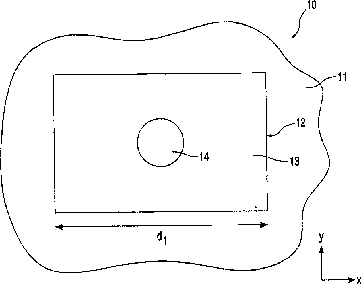
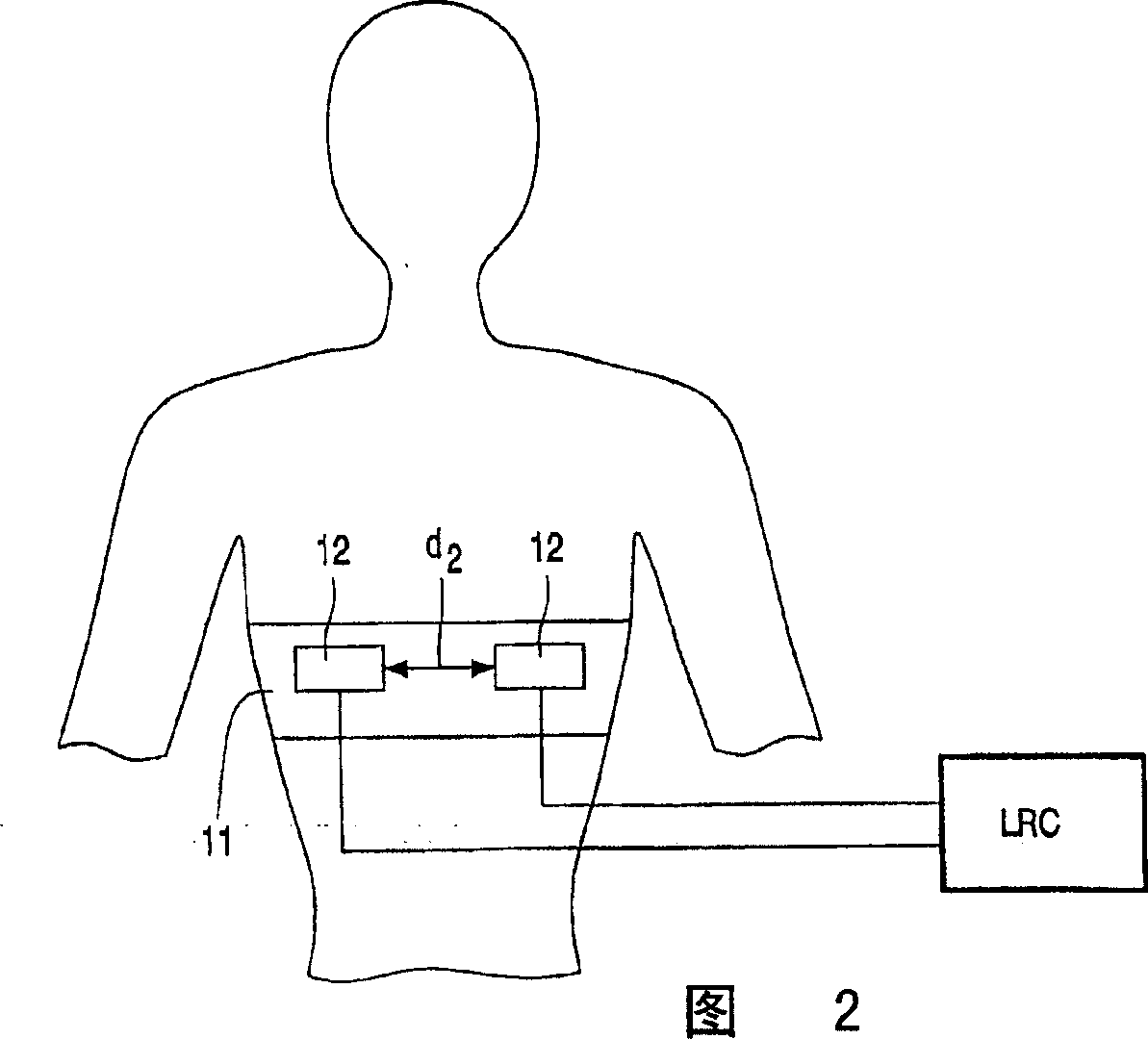
[0029] A first illustrative embodiment of a textile electrode arrangement 10 is shown on a textile article 11 (partially shown), the electrode arrangement comprising a conductive electrode portion 12 shown as a first surface 13, and a portion of material disposed on the first surface 13 14. The first surface 13 and material 14 will be in contact with the skin of the wearer during use of the electrode. This portion of material 14 is substantially moisture impermeable and electrically conductive. In this example, the portion of material 14 comprises silicone rubber loaded with carbon black. This portion of material 14 is ...


PUM

PropertyMeasurementUnit
electrical resistanceaaaaaaaaaa

Abstract

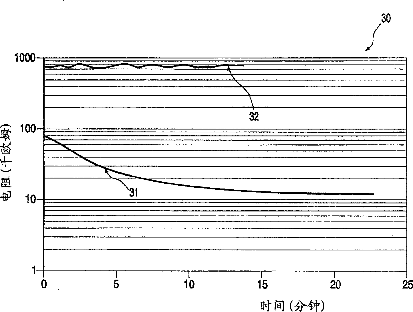
An electrode arrangement (10) comprises a knitted electrically conductive electrode portion (12) containing electrically conductive yarn and at least one portion (14) of moisture impermeable electrically conductive material attached to the electrode portion (12). During use the electrode portion (12) and portion of material (14) are applied to a wearers skin. The moisture impermeable material portion (14) is of silicon loaded with carbon black. The moisture impermeable portion (14) encourages perspiration of a user and the perspiration trapped between the skin and moisture impermeable portion (14) reduces skin to electrode contact resistance to increase efficiency of detection of user heart rate or other electrical signals generated by a user.

Description

technical field [0001] The present invention relates to improved performance of substantially textile-based electrodes. Background technique [0002] WO-A-01 / 02052 relates to a garment comprising at least two regions; one of which is formed by an electrically insulating thread and the other by one or more electrical conductors. The area containing the electrical leads will serve as the electrode surface for contact with the body. The area containing the electrical leads is therefore located on the inside of the garment which contacts the skin of the body. WO-A-01 / 02052 describes that a conductive gel may be used between the area containing the electrical lead and the skin to facilitate electrical contact between the lead and the skin. It is not always desirable to introduce such a gel between the electrode and the skin for many reasons, and it is not always desirable to apply liquids or gels to textiles anyway. [0003] In tests carried out on textile-based electrodes ada...

Claims


Application Information

Patent Timeline
Patent Type & Authority Applications(China)
IPC IPC(8): A61N1/04A61B5/0408D04B1/14
CPCD04B1/14A61B5/04085A61N1/0484A61B5/6831A61B5/0408A61N1/0476A61N1/0472D10B2403/02431A61B5/282A61B5/25A61N1/04A61B5/27A61B5/256
Inventor P·A·高夫M·J·比克尔顿
Owner KONINKLIJKE PHILIPS ELECTRONICS NV
Learn More