Display panel, drive circuit, display device, and electronic equipment

A display panel and drive circuit technology, applied to static indicators, instruments, etc., can solve the problems of residual charges and holding capacitors that cannot be fully discharged, and achieve the effect of preventing charge residues and avoiding deterioration

Active Publication Date: 2006-02-15
SEIKO EPSON CORP
View PDF1 Cites 16 Cited by
  • Summary
  • Abstract
  • Description
  • Claims
  • Application Information

AI Technical Summary

Problems solved by technology

[0004] However, the potential of the common electrode (counter electrode) during normal driving is not necessarily the same potential as the potential of the image signal applied to the DC signal, so there may be a slight amount of DC component applied to the pixel or maintained due to the potential difference. The problem that the capacitor cannot be fully discharged and the residual charge remains

Method used


Image

  • Display panel, drive circuit, display device, and electronic equipment
  • Display panel, drive circuit, display device, and electronic equipment
  • Display panel, drive circuit, display device, and electronic equipment

Examples


Embodiment 1

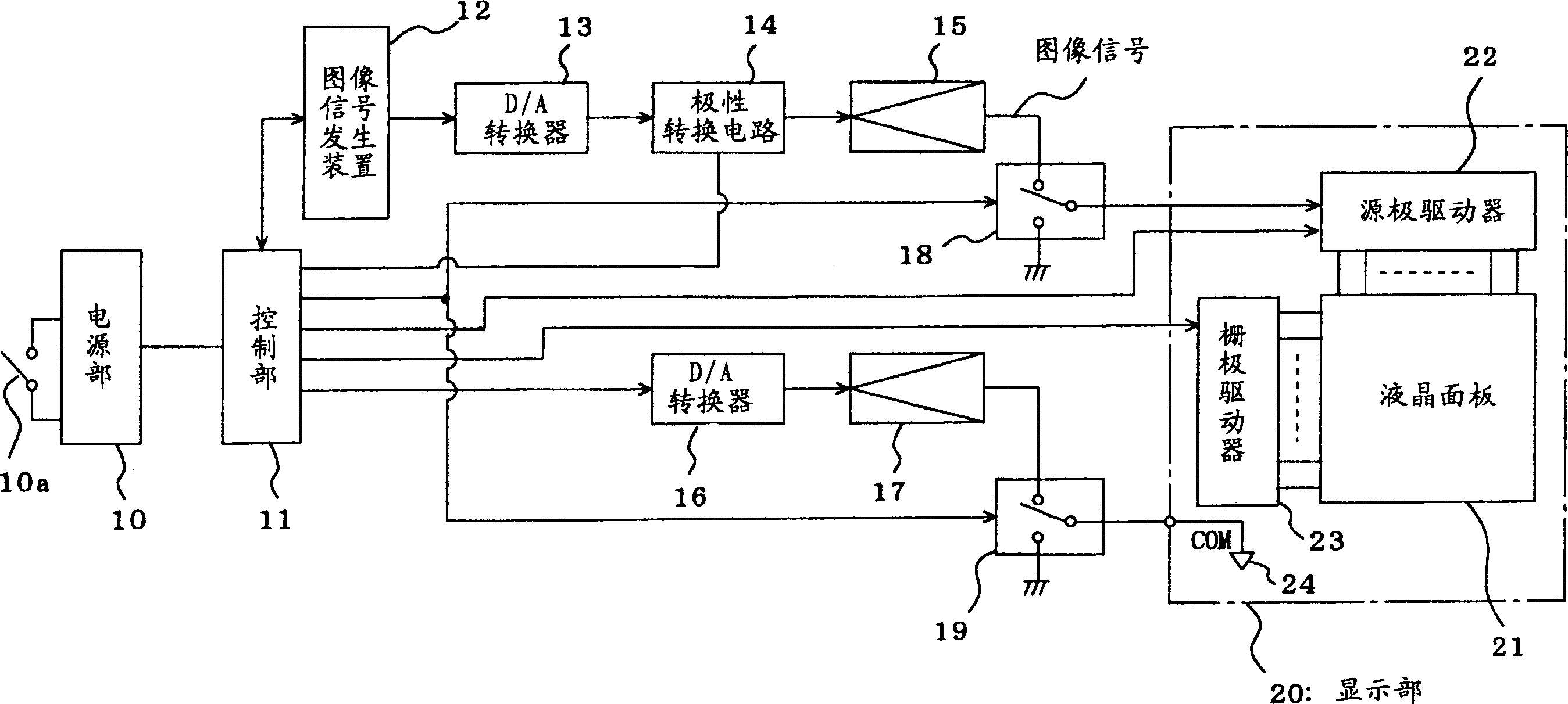
[0024] figure 1 It is a configuration diagram of a display device according to Embodiment 1 of the present invention. This display device is, for example, a device mounted on an electronic device such as a PDA, and has a power supply unit 10, a control unit 11, an image signal generator 12, a D / A converter 13, a polarity conversion circuit 14, an amplifier 15, a D / A A converter 16 , amplifier 17 , switching circuits 18 , 19 and display unit 20 . The display unit 20 has a liquid crystal panel 21 , a source driver 22 and a gate driver 23 . The liquid crystal panel 21 has a structure in which, for example, two transparent substrates such as glass substrates are glued together with a liquid crystal material interposed therebetween, and each pixel is provided with a thin film transistor (TFT) as an active element. In addition, such a liquid crystal panel 21 has, for example, a reflection plate, and displays an image using incident light from the outside.

[0025] The power suppl...

Embodiment 2

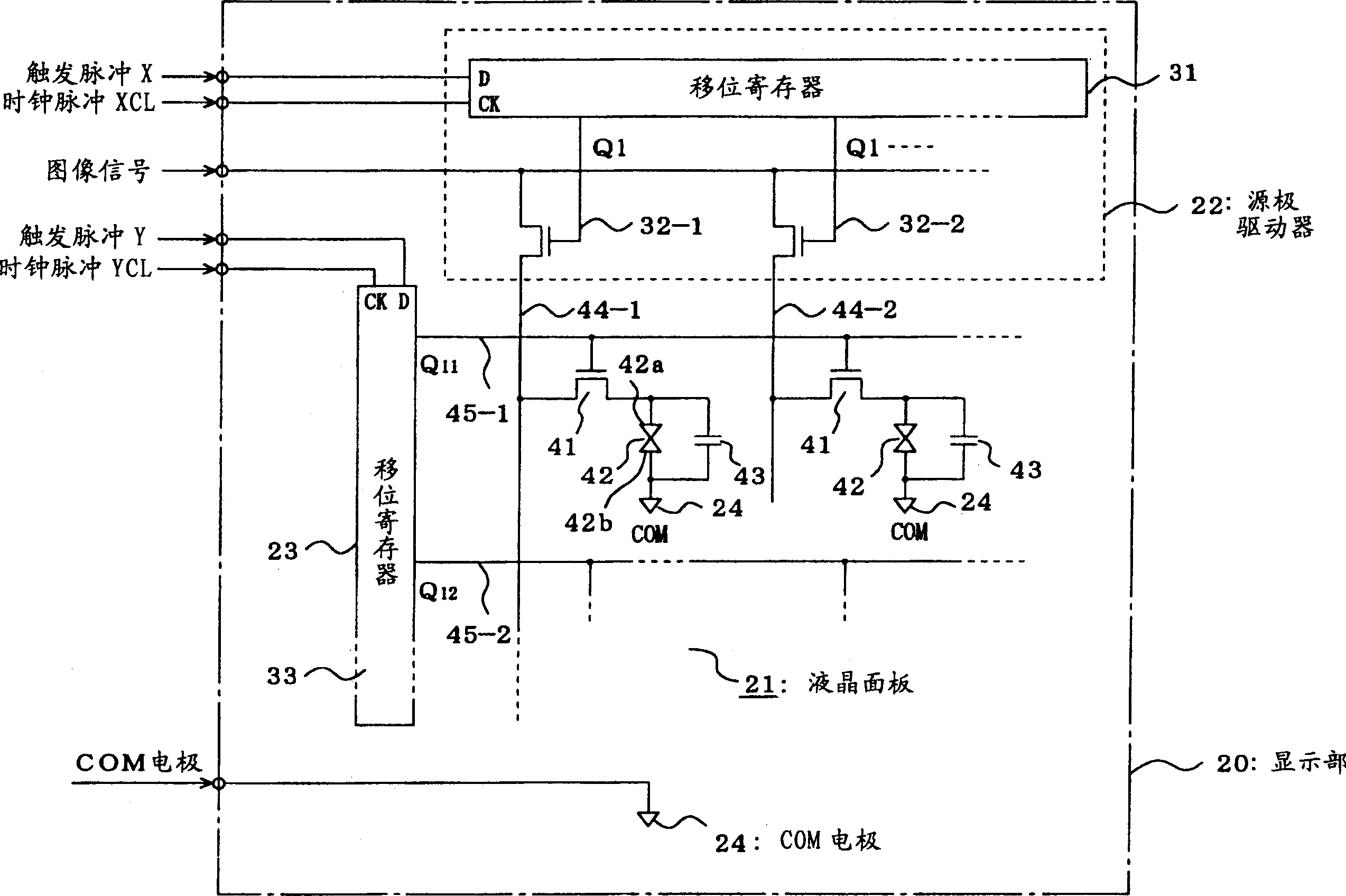
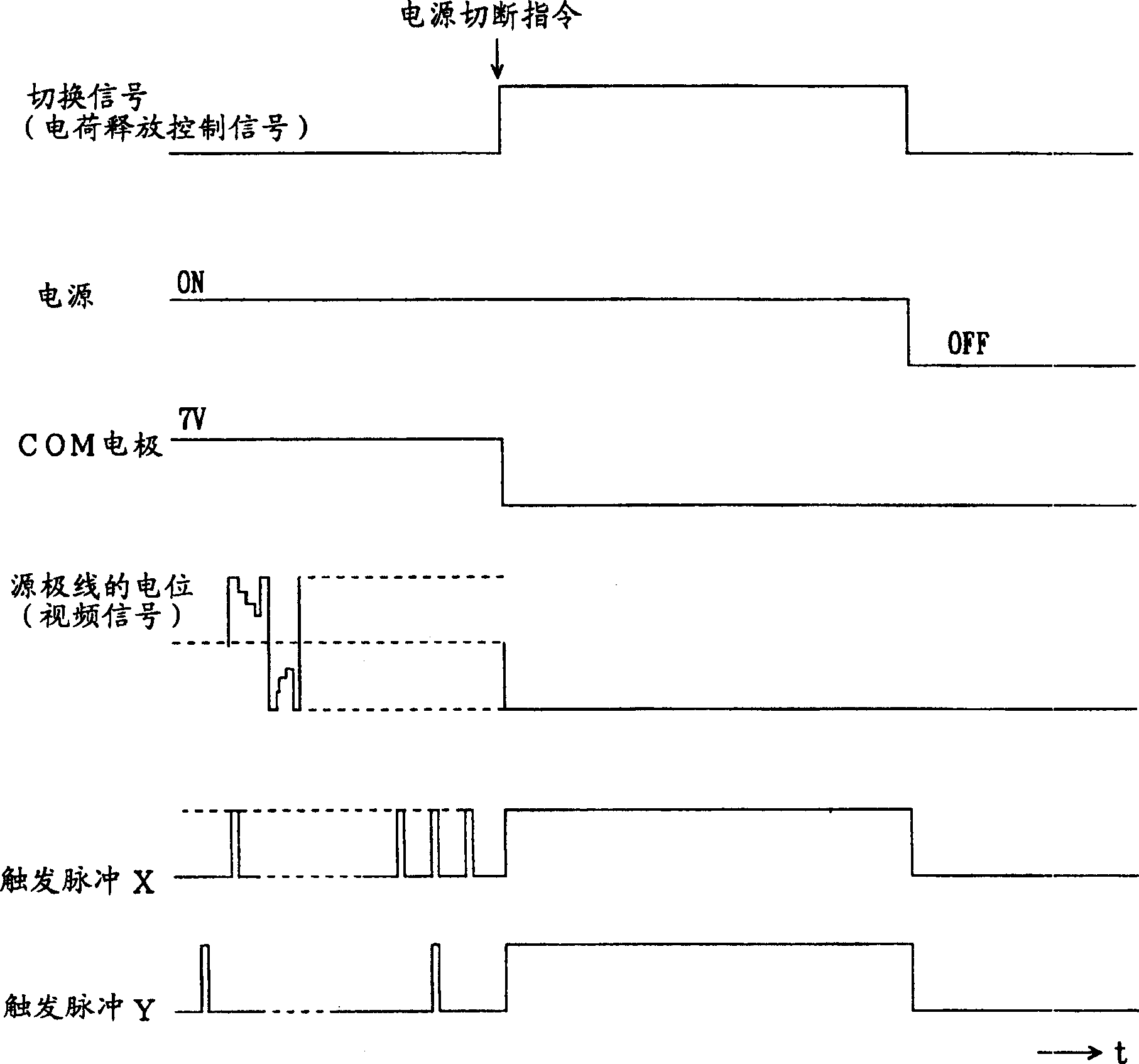
[0034] exist image 3 In the example of , an example in which the power is turned off after the writing process of setting the source lines 44-1, 44-2, ... and the common electrode 24 to the ground potential (0V) is described, but after turning off the power Previously, by turning off all the thin film transistors 41 , it was possible to prevent the pixels from being affected by abnormal image signals accompanying the subsequent power-off. Specifically, by setting the X trigger pulse and the Y trigger pulse at L level for at least one frame, the thin film transistors 41 are gradually turned off, and eventually the thin film transistors 41 of all pixels can be turned off.

Embodiment 3

[0036] In the above-mentioned embodiment, although the example in which the source lines 44-1, 44-2, ... and the common electrode 24 are set to the ground potential (0V) is described, the present invention is not limited to this example. For example, The potential of the source line and the common electrode may be made the same by setting the potential of the common electrode, or the potential of the source line and the potential of the common electrode may be made the same as a DC component of the image signal. In addition, in the above-mentioned embodiments, an example in which all the thin film transistors are turned on in one frame period has been described, but in the present invention, it may be set to be longer than this.

[0037] In addition, as the liquid crystal panel 21, although the example of the reflective type which has a reflector and displays an image using incident light from the outside has been described, the example of a transmissive type which displays an ...


PUM


Abstract

The display device is equipped with the liquid crystal panel 21 equipped with thin film transistors corresponding to respective pixels, a source driver 22 which supplies a video signal to source lines of the thin film transistors, a source driver 23 which supplies a gate voltage to gate lines of the thin film transistors, and a control part 11 which supplies a ground potential to the source lines of the thin film transistors through the source driver 22 instead of the video signal and also supplies the ground potential to a common electrode 24 of the liquid crystal panel after it is commanded that the power source is turned off or after the power source is turned off to control the potential of the source lines and the potential of the common electrode 24 to the same potential for at least one vertical period.

Description

technical field [0001] The present invention relates to a display panel drive circuit for driving a display panel, a display device and electronic equipment incorporating the display panel drive device, and in particular to a display panel in which the display grayscale of each pixel is determined by the accumulated charge between electrodes of each pixel Treatment of residual charges in Background technique [0002] A display panel, such as a liquid crystal panel, requires storage capacitors for maintaining the charge state of its pixels, but on the other hand, it is required to avoid continuously applying a DC voltage to the pixels in order to avoid burn marks of the pixels. In a normal liquid crystal display, although AC driving is performed to avoid applying DC components to the liquid crystal pixels, when the liquid crystal drive circuit starts and stops, the AC driving cannot be performed normally, and DC components are applied to the liquid crystal pixels or remain in...

Claims


Application Information

Patent Timeline
Patent Type & Authority Applications(China)
IPC IPC(8): G09G3/20G09G3/36G02F1/133
CPCG09G2330/026G09G2320/0204G09G3/3614G09G3/3655G09G3/3648G09G3/36
Inventor 佐川隆博小山文夫伊藤长德小林靖幸丸山康东亮介藤原胜美
Owner SEIKO EPSON CORP
Why Eureka
Try Eureka