
Suspended magnetic iron structure of magnetic suspension vehicle and its production mehtod

A technology for levitation magnets and maglev trains, which is applied in vehicle parts, electromagnets, electric vehicles, etc., can solve the problem that the complexity of the cost process cannot meet the requirements of mass production, economic benefits, and can not well meet the requirements of urban traffic passenger flow and vehicle load. Insufficient passenger capacity and other problems, to achieve the effect of being beneficial to protection, ensuring insulation performance and quality, and improving electromagnetic attraction and suspension force

Active Publication Date: 2006-02-22
TONGJI UNIV
View PDF8 Cites 12 Cited by
  • Summary
  • Abstract
  • Description
  • Claims
  • Application Information

AI Technical Summary

Problems solved by technology

[0005] According to the descriptions of short stator maglev vehicles in US5152227, JP3-30366, JP63-209406 and other patents, most of the levitation electromagnets 4 of existing maglev vehicles are single-coil structures, and the number of coil turns is limited by the overall size of the vehicle. The passenger capacity of the vehicle is insufficient, which cannot meet the requirements of the peak passenger flow of urban traffic.
If the excitation current is increased to improve the levitation ability, it will cause the overheating of the levitation coil. Although many holes have been drilled on the levitation magnet core as cooling by the air flow of the train (see JP62-210807 patent), no significant effect has been seen. the result of
[0006] In addition, in terms of the design and manufacture of the levitation magnet core, there is no public technical data showing that levitation magnets with a split assembly structure are mostly manufactured by welding and machining methods, which cannot meet the requirements of large manufacturers in terms of cost and process complexity. Requirements for mass production and economic benefits
This is also a factor in the high cost of urban rail maglev trains

Method used


Image

  • Suspended magnetic iron structure of magnetic suspension vehicle and its production mehtod
  • Suspended magnetic iron structure of magnetic suspension vehicle and its production mehtod
  • Suspended magnetic iron structure of magnetic suspension vehicle and its production mehtod

Examples


Embodiment Construction

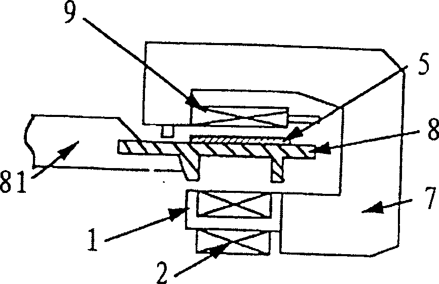
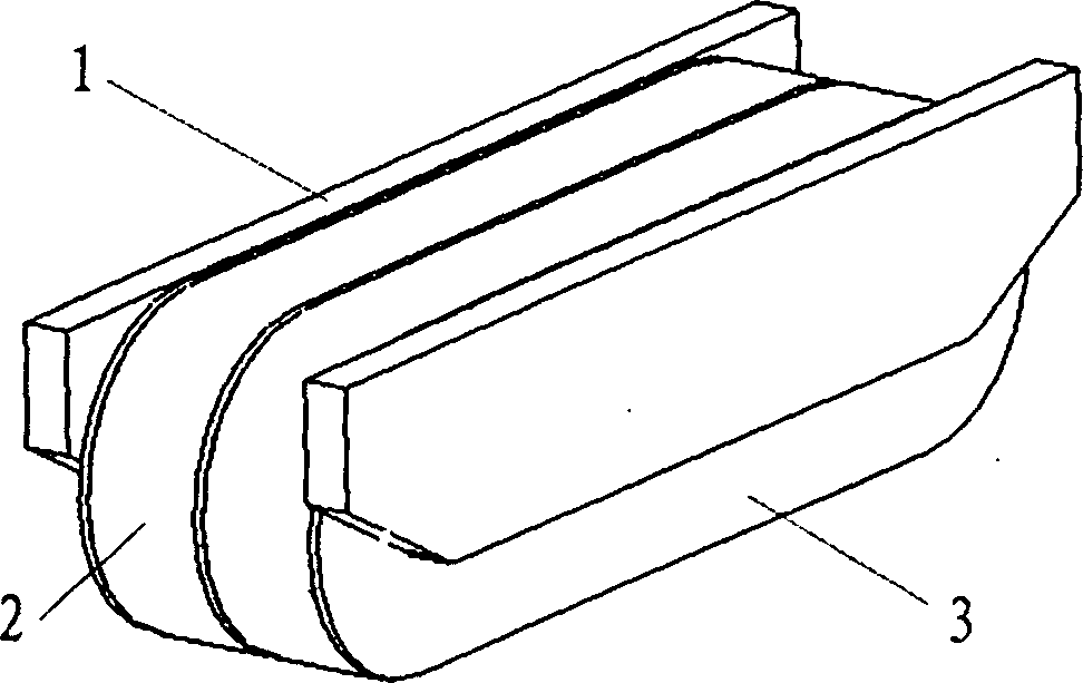
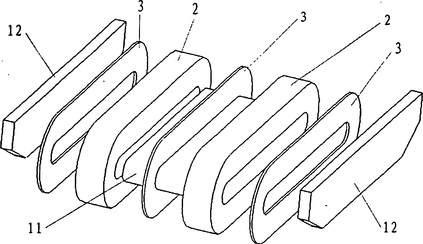
[0036] see figure 2 and image 3 As shown, the suspension magnet of the present invention is composed of an iron core 1 , a coil 2 and a cooling jacket 3 . The iron core 1 is a split combined structure, which is composed of two magnetic poles 12 located on both sides and a magnetic pole 11 located in the middle of the two magnetic poles 12 and connected to one end of the two magnetic poles 12 respectively, and is fixed on the Together, they form an iron core with a circular cross-section. The coil 2 is wound from a 0.15-0.30mm thick aluminum foil 22 and a 0.01-0.03mm thick insulating film 21 (such as a polyurethane film). The present invention replaces the general enameled wire with aluminum foil, so that the coil can withstand a larger excitation current . The coil 2 is set on the magnet 11, and the number of the coil 2 can be one, but in order to increase the number of turns of the coil 2 and the effect of cooling in a limited space, it is preferable to divide it into tw...


PUM


Abstract

Disclosed is a suspending magnet structure of magnetic levitation vehicle, which contains an iron core and a coil and is characterized in that: the coil is prepared with aluminum foil of thicken of 0.15- 0.30mm and insulation film of thicken of 0.01- 0.03mm; the two-side of the coil being separately equipped with copper coolant jacket, inside which is equipped with coiling passage and outside of which is equipped with a pipe connector connecting separately with the two ends of the passage. The invention makes the coil of the suspending magnet cool down effectively and improves the number of turns of coil and the property of resisting big current.

Description

Technical field: [0001] The invention belongs to the levitation magnet structure and its manufacturing technology of a vehicle with the conventional electromagnetic levitation technology. Background technique: [0002] Maglev vehicles can be divided into electromagnetic suspension (EMS-electromagnetics suspension) and electric suspension (EDS-electrodynamic suspension) in terms of suspension mechanism. Electromagnetic Suspension (EMS) is to energize and excite the vehicle-mounted suspension electromagnet (or permanent magnet plus excitation control coil) to generate an electromagnetic field, and the electromagnet and the ferromagnetic component on the track (steel track or long stator linear motor stator core) attract each other , Suction the train upwards and suspend it on the track. The suspension gap between the electromagnet and the ferromagnetic track is generally about 8-10mm. Electric Suspension (EDS) means that the train can only be suspended when it reaches a certa...

Claims


Application Information

Patent Timeline
Patent Type & Authority Applications(China)
IPC IPC(8): B60L13/00B60L13/04H01F7/06
Inventor 吴祥明何大海彭显付
Owner TONGJI UNIV
Learn More