LED lamp for improving heat radiation effect

A technology for LED lights and heat dissipation effects, which is applied in lighting and heating equipment, semiconductor devices of light-emitting elements, cooling/heating devices of lighting devices, etc., and can solve the problem of heat dissipation of LED lights, poor effect, and insufficient brightness of single-chip LEDs And other issues

Inactive Publication Date: 2006-02-22
周应东
View PDF6 Cites 52 Cited by
  • Summary
  • Abstract
  • Description
  • Claims
  • Application Information

AI Technical Summary

Problems solved by technology

Considering the insufficient brightness of a single LED, LED lights generally adopt an LED array structure, which creates the problem of heat dissipation for LED lights
[0003] In the Chinese Patent Application Publication No. CN1277665A document, a kind of LED lamp heat dissipation scheme is disclosed, in which the heat dissipation is to absorb the heat of the base connected to the LED through the connecting column in the lamp body, and then still dissipate heat in the lamp body, because it is Many times of indirect heat dissipation, and heat dissipation in the closed lamp body, the effect is not good
[0004] In the Chinese Patent Application Publication No. CN1359137A document, a heat pipe lamp heat dissipation scheme is disclosed. In this scheme, the heat dissipation of the scheme is to absorb the heat of the light emitting device through one end of the superconducting heat pipe, and transfer the heat to the heat sink of the lamp body in contact with the air at the other end. , because it is still multiple indirect heat dissipation, the effect is still not good
[0005] In the Chinese patent authorization announcement number CN2557805Y document, a high-power LED lamp heat dissipation scheme is disclosed. In this scheme, the

Method used


Image

  • LED lamp for improving heat radiation effect
  • LED lamp for improving heat radiation effect
  • LED lamp for improving heat radiation effect

Examples


Embodiment 1

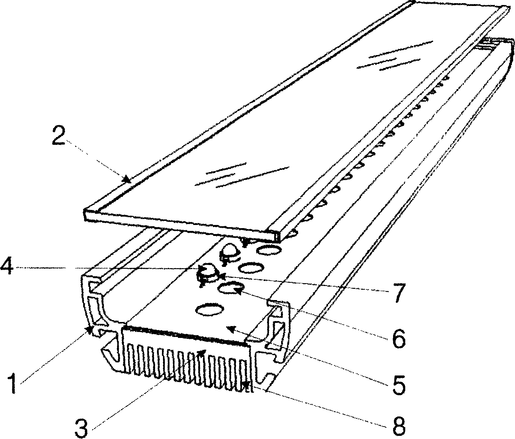
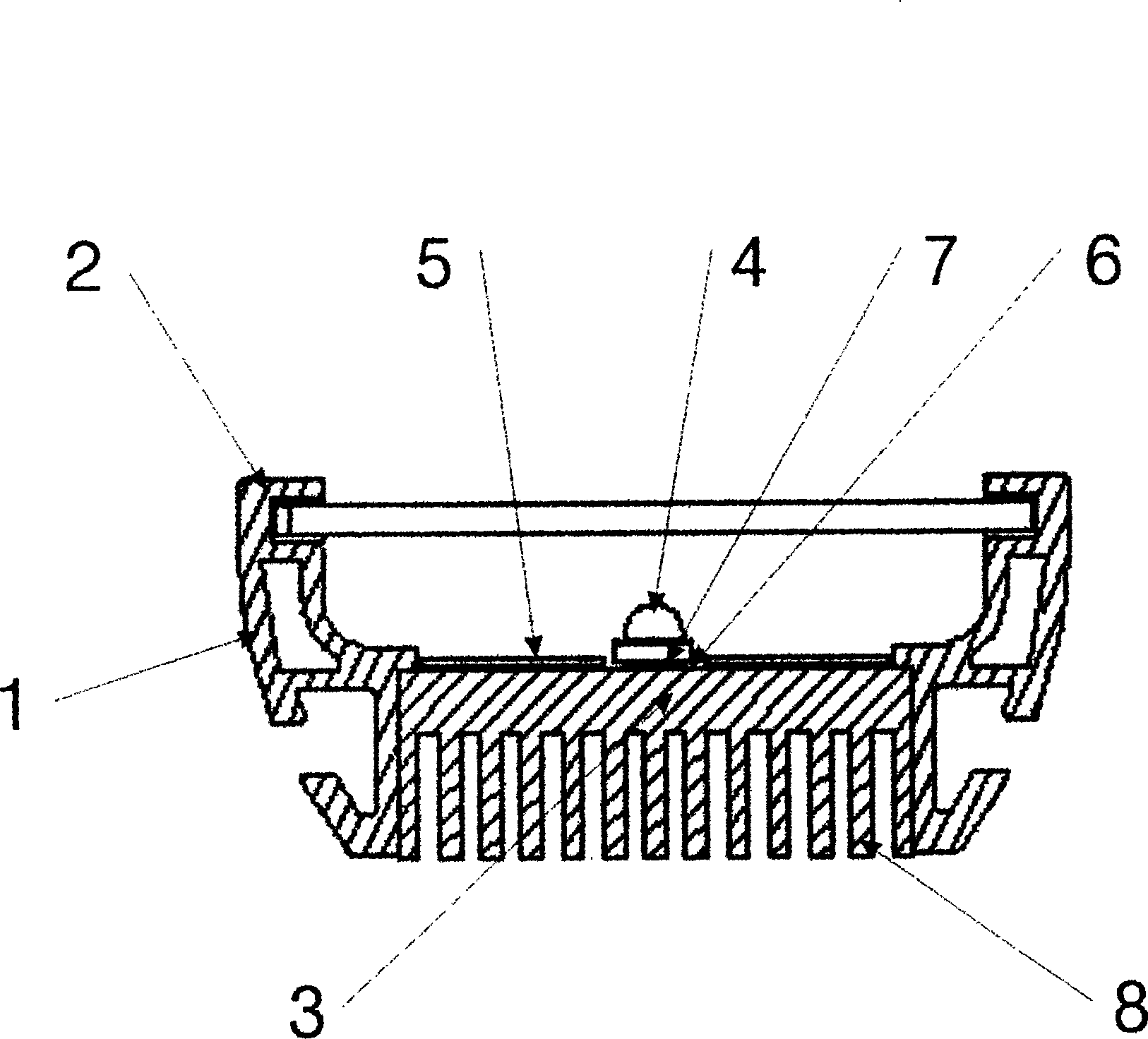
[0024] Example 1 as figure 1 , figure 2 shown. The LED wall washer is in the shape of a strip, on which a row of single-chip LEDs (4) are arranged along the direction of the strip; the heat sink (7) of the LED tube body of each LED (4) passes through the strip-shaped printed circuit board (5 ) is in direct thermal contact with the strip-shaped lamp housing bottom cover (3), and most of the heat of the LED (4) is directly transferred from the heat sink (7) of the LED tube body to the (4) The lamp housing bottom cover (3) of the secondary heat sink, the lamp housing bottom cover (3) and the heat sink (8) on it are all directly exposed to the air or soil (including various walls) to dissipate heat; The tube body of the LED (4) emits LED light to the outside of the lamp housing through the lamp housing cover (2); the area of ​​the lamp housing bottom cover (3) is slightly larger than the area of ​​the printed circuit board (5); The lamp housing bottom cover (3) and heat dissip...

Embodiment 2

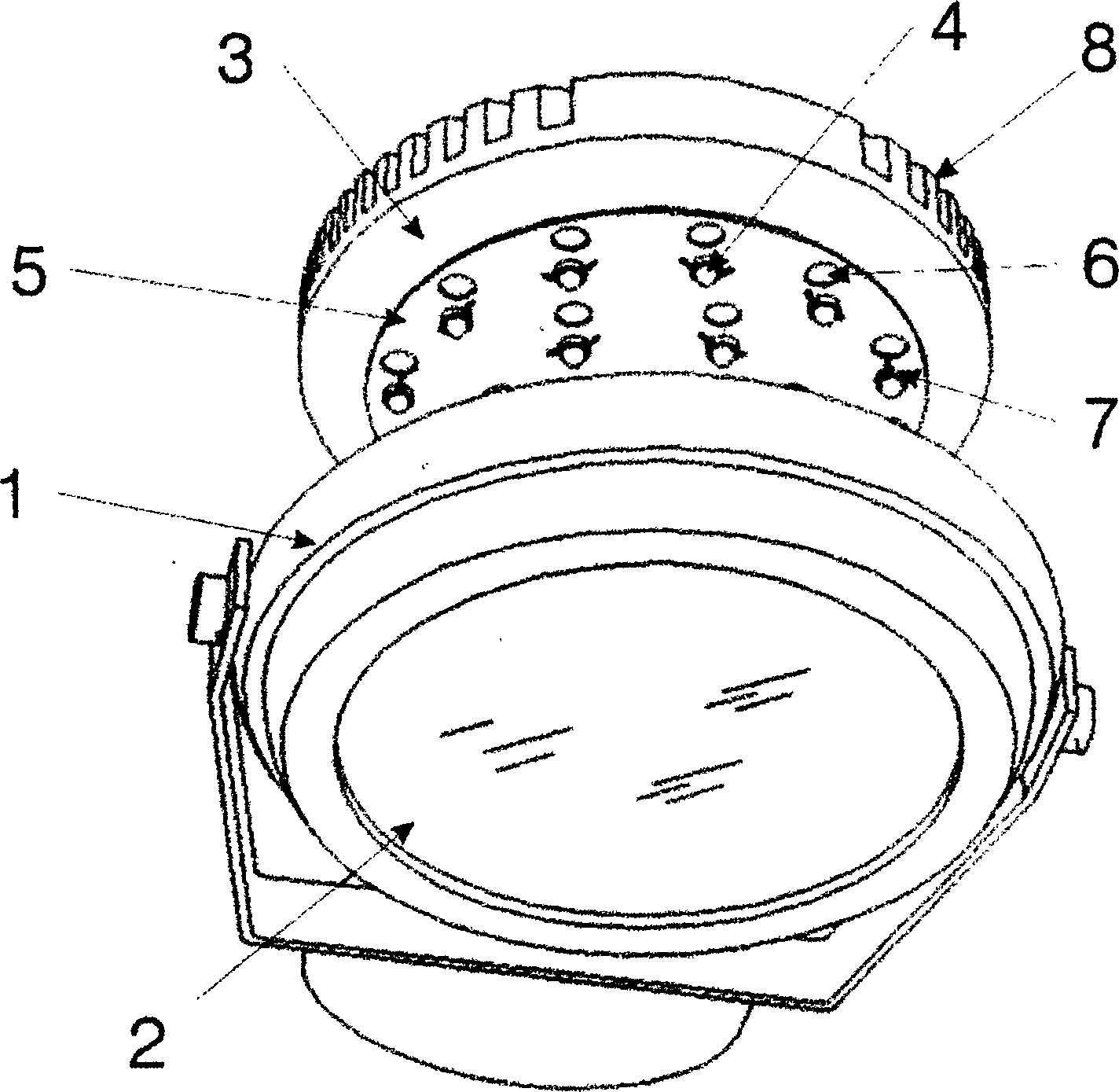
[0026] Example 2 as image 3 , Figure 4 shown. The LED spotlight is circular, on which there are arrayed single-chip LEDs (4); the LED tube body heat sink (7) of each LED (4) passes through the corresponding socket on the circular printed circuit board (5) The accommodating hole (6) is in direct thermal contact with the circular lamp housing bottom cover (3), and most of the heat of the LED (4) is directly transferred from the heat sink (7) of the LED tube body to the second stage of the LED (4). The circular lamp housing bottom cover (3) of the heat sink, the lamp housing bottom cover (3) and the heat dissipation fins (8) on it are directly exposed to the air, water or soil for heat dissipation; each LED (4) tube body The LED light is emitted outside the lamp housing through the lamp housing cover (2); the area of ​​the lamp housing bottom cover (3) is slightly larger than the area of ​​the printed circuit board (5), so that the printed circuit board (5) Installed in the ...

Embodiment 3

[0028] Example 3 as Figure 5 , Figure 6 shown. The lamp head of the LED street lamp is circular, on which a single piece of LED (4) is arrayed; the heat sink (7) of the LED tube body of each piece of LED (4) passes through the corresponding accommodation hole (6) on the circular printed circuit board (5) ) is in direct thermal contact with the circular lamp housing bottom cover (3), and most of the heat of the LED (4) is directly transferred from the LED tube body heat sink (7) to the lamp housing as the secondary heat sink of the LED (4) The bottom cover (3), the bottom cover of the lamp housing (3) and the heat dissipation fins (8) on it are directly exposed in the air to dissipate heat; LED light is emitted from the outside of the housing; the area of ​​the lamp housing bottom cover (3) is slightly larger than that of the printed circuit board (5), so that the printed circuit board (5) is installed in the lamp housing body (1); The lamp housing bottom cover (3) and its...


PUM


Abstract

This invention relates to a LED light which can improve heat radiation effect. The light comprises a lamp body (1), a lamp body bottom cap (3), or a lamp body face cap (2), wherein the lamp body (1) can integrate the lamp body bottom cap (3) or the lamp body face cap (2) into a whole; the light also comprises a circuit which ha LED (4), electronic component and corresponding normal PCB printed circuit board (5); the circuit is in the lamp body or in the inner cavity of the lamp body bottom cap (3) or in the lamp body face cap (2); the printed circuit board has the corresponding filling hole with the LED (4), the LED pipe heat sink (7) will pass through the filling hole (6) and contact with the lamp body bottom cap (3) or lamp body (1) or lamp body face cap (2), forming the heat emission channel of the LED (4). By said invention, it can emit heat directly to air or water or earth.

Description

technical field [0001] The invention relates to an LED lamp with improved heat dissipation effect, in particular to an array type high-power LED lamp. Background technique [0002] LED has the advantages of low energy consumption, low heat generation and long service life, and can completely replace traditional light sources. Considering that the luminance of a single LED is insufficient, the LED lamp generally adopts an LED array structure, which causes the problem of heat dissipation of the LED lamp. [0003] In the Chinese Patent Application Publication No. CN1277665A document, a kind of LED lamp heat dissipation scheme is disclosed, in which the heat dissipation is to absorb the heat of the base connected to the LED through the connecting column in the lamp body, and then still dissipate heat in the lamp body, because it is Multiple times of indirect heat dissipation, and heat dissipation in the closed lamp body, the effect is not good. [0004] In the Chinese Patent A...

Claims


Application Information

Patent Timeline
IPC IPC(8): F21S8/00F21V29/00F21W131/00F21Y101/02F21V29/51F21V29/76F21Y115/10
Inventor 周应东
Owner 周应东
Why Eureka
Try Eureka