Dirt monitoring device

A monitoring device and fouling technology, applied in measurement devices, material analysis by optical means, instruments, etc., can solve the problems of reducing the flow cross-sectional area, clogging the pipeline, reducing the operating economy of the equipment, etc., achieving easy and direct access, fouling description Intuitive, easy-to-measure effects

A monitoring device and fouling technology, applied in measurement devices, material analysis by optical means, instruments, etc., can solve the problems of reducing the flow cross-sectional area, clogging the pipeline, reducing the operating economy of the equipment, etc., achieving easy and direct access, fouling description Intuitive, easy-to-measure effects

CN1737574AInactive Publication Date: 2006-02-22NORTH CHINA ELECTRIC POWER UNIV (BAODING)

Image

  • Dirt monitoring device
  • Dirt monitoring device
  • Dirt monitoring device

Examples


Embodiment Construction

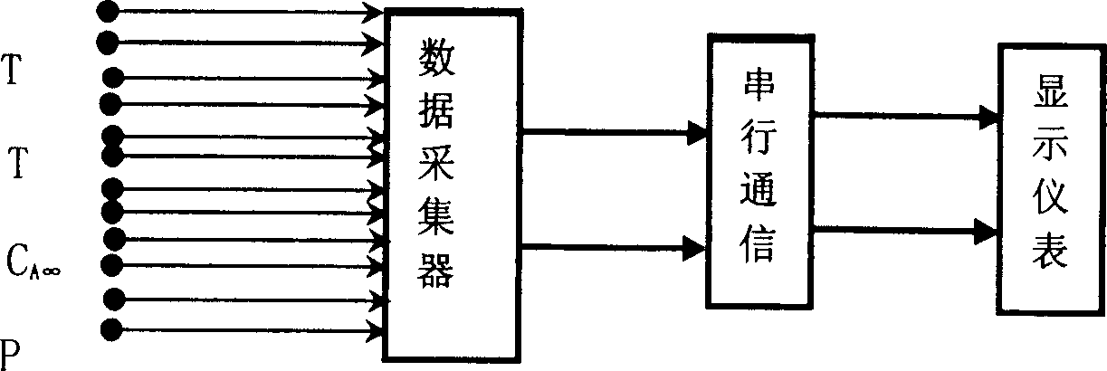
[0020] When the fluid flows in the measured pipe section, there are eight temperature measuring points arranged on the inner surface. The eight chip temperature sensors are arranged according to the principle of equal division, and can be bonded to the pipe wall along the flow direction, and the outlet points should be tightly sealed. , to prevent liquid leakage, and pay attention to the interference between the lines. An isolator can be installed as needed. The resistance signal measured by the temperature sensor is converted into a voltage signal after resistance conditioning, and then converted into a digital signal through analog-to-digital conversion. The pressure sensor is installed on the upper part of the pipe section at the entrance and exit, and the lead-out line should also prevent the fluctuation of the grounding point potential from causing the fluctuation of the analog signal. If necessary, an isolator should be installed, and the output current signal is converted...


PUM


Abstract

This invention provides one dirty monitoring device in engineer heat physical and energy utilization field, which comprises temperature sensor, pressure sensor and concentration sensor, data collector and display meter, wherein, the temperature sensor is to detect inside wall temperature of tube with 8 to 12 spots measured; the pressure sensor is to measure the pressure loss of the tube section; the concentration sensor is to measure dirty suspension or salt main concentration. The data through A / D conversion are combined with relative data for computing and correcting.

Description

technical field [0001] The patent of the invention belongs to the field of engineering thermophysics and energy utilization, and provides a dirt monitoring device, which is widely used in the thermal equipment industry of fluid transportation and energy transfer. Background technique [0002] Most of the current monitoring models of fouling are formed based on heat exchange theory, and the result of the ratio of temperature difference to heat flow—fouling thermal resistance—is the ultimate goal of monitoring, so as to measure the impact on the heat transfer effect and make decisions. But it also brings some problems. First of all, for the non-heat exchange situation, because the temperature difference is zero, it is obviously impossible to use the dirt thermal resistance to measure the dirt deposition. This situation also exists in many industries, such as power, chemical industry The pipeline transportation of pure multi-phase flow and the isothermal flow of multi-component...

Claims


Application Information

Patent Timeline
22 Feb 2006
Publication
CN1737574A
IPC
G01N35/00; G01N21/00
Inventors
程伟良