Regulator circuit capable of detecting variations in voltage
A regulator circuit and detection circuit technology, applied in the direction of adjusting electrical variables, control/regulation systems, instruments, etc., can solve problems such as slow response speed and difficulty in suppressing output voltage changes
- Summary
- Abstract
- Description
- Claims
- Application Information
AI Technical Summary
Problems solved by technology
Method used
Image
Examples
no. 1 approach
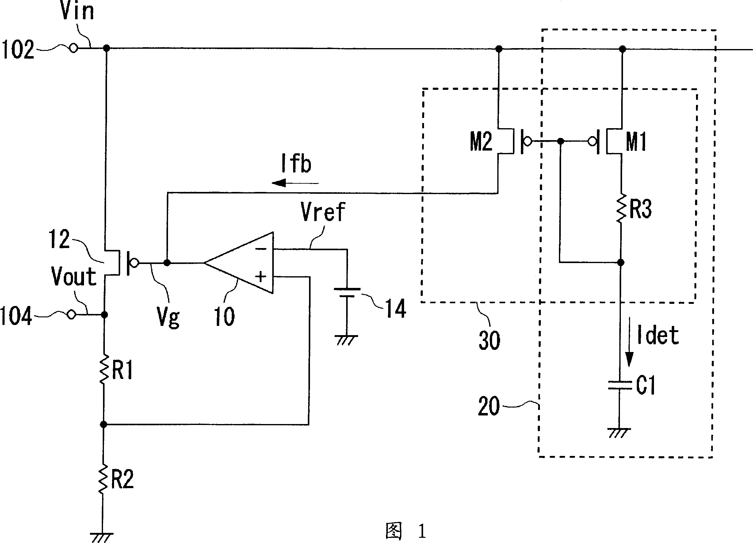
[0044] FIG. 1 shows the configuration of a regulator circuit 100 according to the first embodiment. In the following figures, the same components are given the same reference numerals, and explanations thereof are appropriately omitted.
[0045] The regulator circuit 100 of this embodiment includes a detection circuit 20 and an auxiliary circuit 30 in addition to the error amplifier 10 , the output transistor 12 , the first resistor R1 , the second resistor R2 , and the reference voltage source 14 . In addition, the regulator circuit 100 includes an input terminal 102 and an output terminal 104 , and the voltages applied or presented to the respective terminals are respectively referred to as an input voltage Vin and an output voltage Vout.
[0046] The error amplifier 10, the output transistor 12, the first resistor R1 and the second resistor R2 constitute a general linear regulator.
[0047] The output transistor 12 is provided between the input terminal 102 and the output ...
no. 2 approach
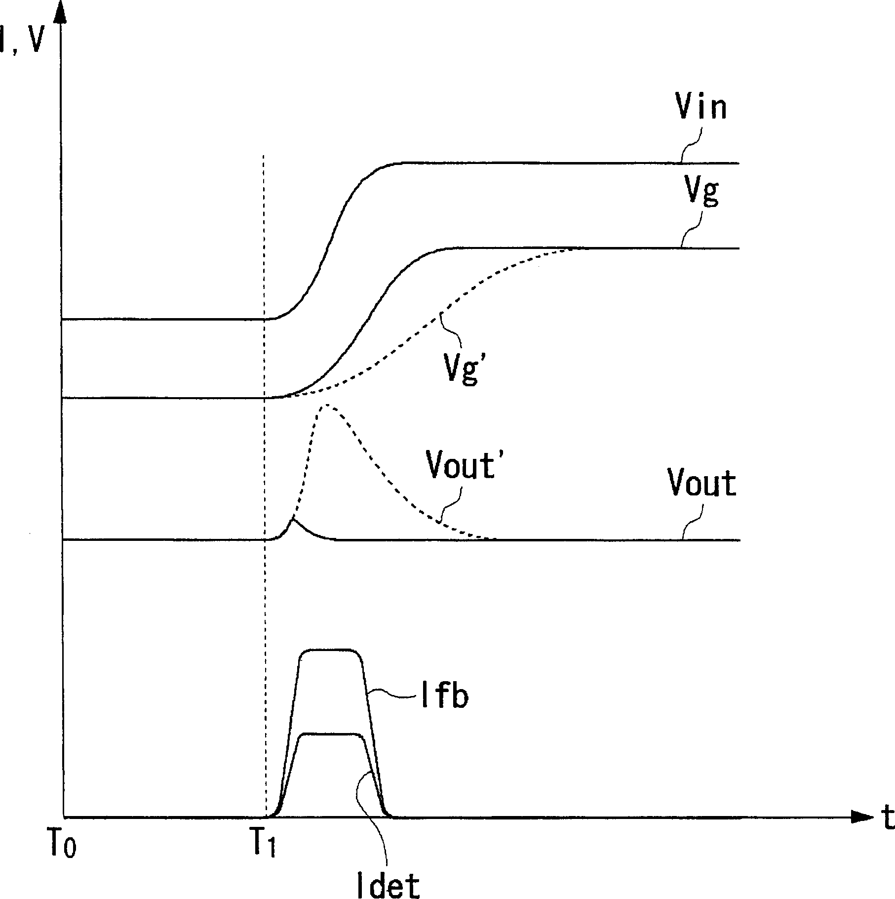
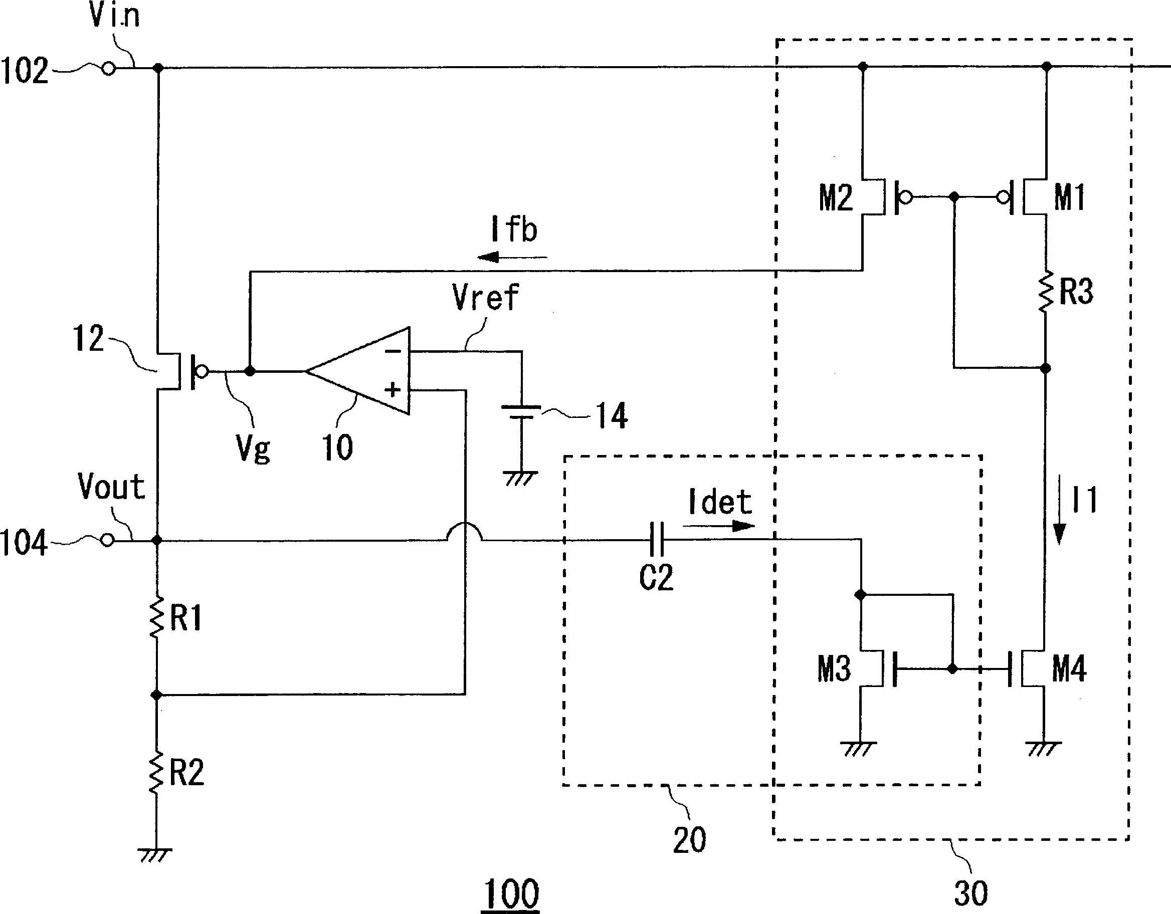
[0070] In the first embodiment, overshooting is suppressed by feeding back the circuit variation detected by the detection circuit 20 to the gate terminal of the output transistor 12 . In the second embodiment to be described below, by feeding back the voltage variation detected by the detection circuit 20 to the error amplifier 10 constituting the regulator circuit 100, the gain of the error amplifier 10 is increased to speed up the response speed, so that only when the circuit is in a transient state Improve the responsiveness of the regulator circuit.
[0071] Figure 4 The structure of the regulator circuit 100 of the second embodiment is shown. The regulator circuit 100 includes an error amplifier 10 , an output transistor 12 , a reference voltage source 14 , a first resistor R1 , a second resistor R2 , a detection circuit 20 , and an auxiliary circuit 40 .
[0072] The detection circuit 20 is connected to the input terminal 102 and detects fluctuations in the input vol...
PUM
 Abstract
Description
Claims
Application Information
 - R&D
- Intellectual Property
- Life Sciences
- Materials
- Tech Scout
- Unparalleled Data Quality
- Higher Quality Content
- 60% Fewer Hallucinations
Browse by: Latest US Patents, China's latest patents, Technical Efficacy Thesaurus, Application Domain, Technology Topic, Popular Technical Reports.
© 2025 PatSnap. All rights reserved.Legal|Privacy policy|Modern Slavery Act Transparency Statement|Sitemap|About US| Contact US: help@patsnap.com


