Gear type machining tip and tool attaching the same thereon

A tip, workpiece technology, applied in stone processing tools, sawing machine tools, manufacturing tools, etc., can solve problems such as increased cutting load, shank bending, and excessive processing load.

Inactive Publication Date: 2006-03-01
NIWA DAIYAMONDO INDS
View PDF4 Cites 3 Cited by
  • Summary
  • Abstract
  • Description
  • Claims
  • Application Information

AI Technical Summary

Problems solved by technology

In the case where the cutting tool is applied to a machine for continuous use under fixed machining conditions (e.g., feed rate, depth of cut, and rotational speed), the cutting load suddenly increases, thereby applying excessive force to both the tool and the machine. processing load
As a result, the shank may be bent, the cutting tool may not be able to machine the workpiece into the desired shape, or the cutting tool may be damaged

Method used


Image

  • Gear type machining tip and tool attaching the same thereon
  • Gear type machining tip and tool attaching the same thereon
  • Gear type machining tip and tool attaching the same thereon

Examples


Embodiment Construction

[0070] Reference will now be made in detail to the preferred embodiments of the invention, examples of which are shown in the accompanying drawings.

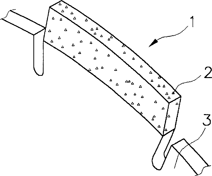
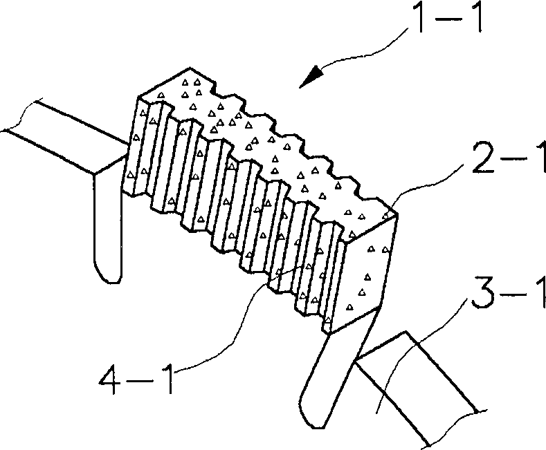
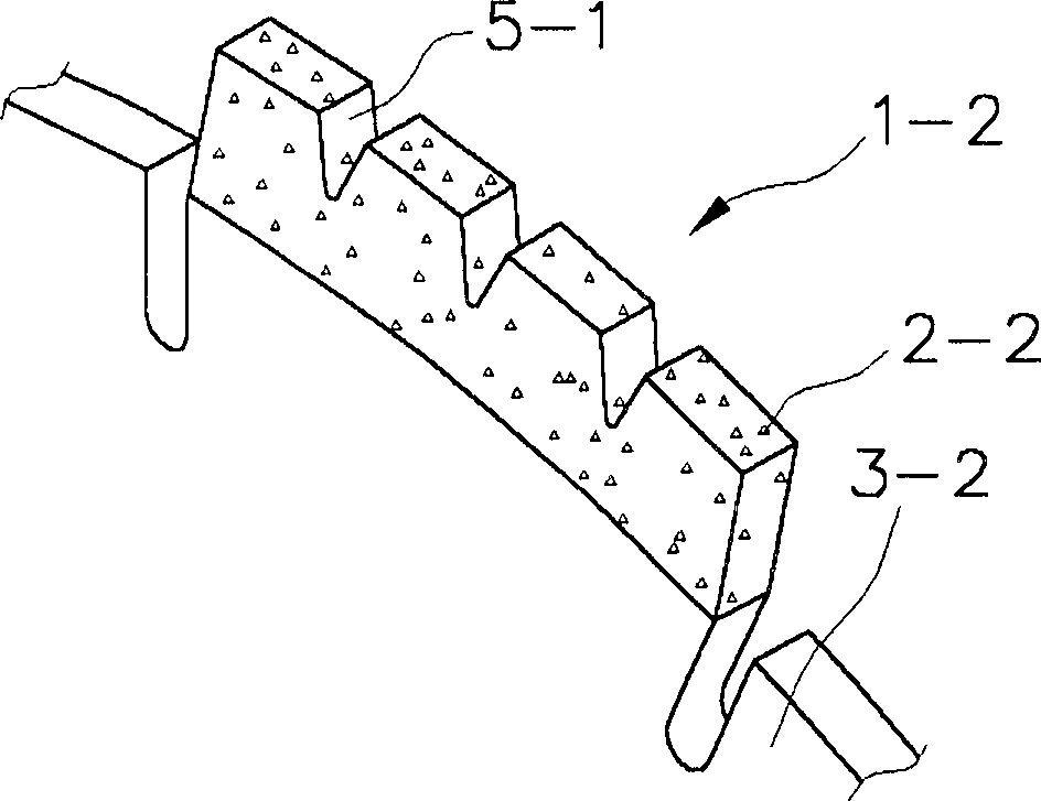
[0071] The sawtooth-shaped cutting tip of the present invention having a double-layer structure includes: an adhesive layer containing super wear-resistant particles therein and having grooves formed on the working surface in contact with the workpiece; and a spacer layer with For attaching the adhesive layer to the handle. The zigzag cutting tip of the present invention is divided into a segmented cutting tip and a continuous rim cutting tip. In addition, the cutting tip of the present invention is mounted on the outer periphery of the cutting tool of the present invention, which is classified into a cutting tool, a grinding tool, and a drilling tool according to functions. A preferred embodiment of the invention will be described below with reference to a segmented cutting tip, but this is done by way of example only.

[007...


PUM

PropertyMeasurementUnit
widthaaaaaaaaaa

Abstract

The invention relates to a serrated cutting tip and a serrated cutting tool having the cutting attached thereto capable of working a work piece at a fixed workability. The cutting tip includes a bond layer, which has super abrasive particles contained therein and grooves formed on a face which is in contact with the work piece, and a blank layer for strongly supporting the bond layer, by which a working plane of the cutting tip contacting the work piece is uniformly maintained during working use and debris can be readily discharged. As a result, workability is improved and lifetime is prolonged.

Description

technical field [0001] The present invention relates to a cutting tool for cutting, grinding or drilling workpieces such as concrete or stone, and more particularly to a serrated cutting tip with a double-layer structure capable of processing workpieces at a predetermined processing speed , and a serrated cutting tool on which the cutting tip is mounted. Background technique [0002] First, general definitions are given for terms in the specification, which will be used consistently throughout the specification. [0003] Superabrasives or superabrasive particles refer to superhard particles usually formed of diamond or cubic boron nitride (CBN) having a relatively high hardness. [0004] The cutting tip refers to the main body for grinding or cutting workpieces, which is made by a manufacturing process including the step of mixing super wear-resistant particles with a binder, and is divided into a segmented tip and a continuous rim tip. [0005] The segmented cutting tip i...

Claims


Application Information

Patent Timeline
Patent Type & Authority Applications(China)
IPC IPC(8): B28D1/12B23D61/02B23D61/04B24D5/12B24D99/00B28D1/04
CPCB28D1/041B24D5/123B24D99/005B28D1/121B23D61/023B28D1/12
Inventor 金秀光李昌弦崔仁硕
Owner NIWA DAIYAMONDO INDS
Why Eureka
Try Eureka