One cycle control continuous conduction mode PFC boost converter integrated circuit with integrated power switch and boost converter

A technology of integrated circuits and control circuits, applied in the field of PFC boost converter integrated circuits with single-cycle control continuous conduction mode of power switches and boost converters, which can solve problems such as difficult design and complex design of the number of components

Inactive Publication Date: 2006-03-01
INFINEON TECH AMERICAS CORP
View PDF4 Cites 16 Cited by
  • Summary
  • Abstract
  • Description
  • Claims
  • Application Information

AI Technical Summary

Problems solved by technology

[0003] Disadvantages of the above prior art approach using multipliers are the high discrete component count and complex design and development work required to achieve high performance continuous conduction...

Method used


Image

  • One cycle control continuous conduction mode PFC boost converter integrated circuit with integrated power switch and boost converter
  • One cycle control continuous conduction mode PFC boost converter integrated circuit with integrated power switch and boost converter
  • One cycle control continuous conduction mode PFC boost converter integrated circuit with integrated power switch and boost converter

Examples


Embodiment Construction

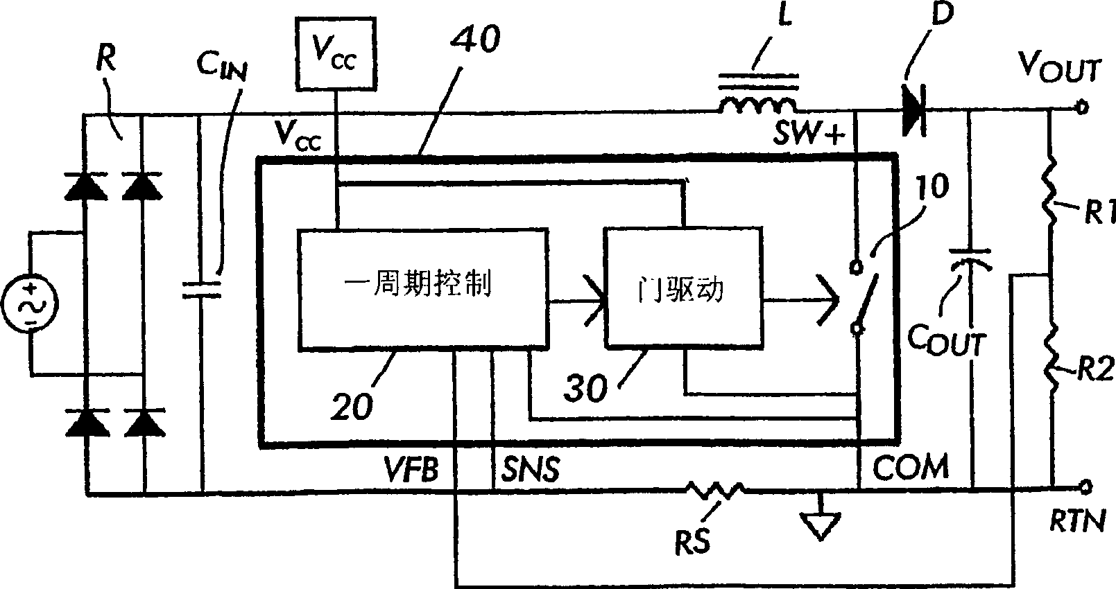
[0015] figure 2 A system-level block diagram of the present invention is depicted, which represents the OCC-based active power factor correction technique operation of continuous conduction mode boost converter technology at a fixed frequency.

[0016] In CCM, the current in the inductor is never allowed to go to zero. According to the present invention, the power switch 10 and the PFC control circuit 20 based OCC and power switch driver 30 are integrated in a single package 40 capable of dissipating appropriate heat from the device to the heat sink. Since the number of pins needed to implement a complete CCM PFC boost converter is reduced by using OCC technology, various power packages can be used using this technology.

[0017] The control circuit 20 is based on the method of OCC in which the multipliers and input voltage detection mentioned in the prior art are not required. This results in fewer enclosed pins and external components for IC 40 . The concept of OCC can be...


PUM


Abstract

An integrated circuit for a continuous conduction mode (CCM) power factor corrected boost converter circuit, the boost converter circuit including a rectifier connectable to an ac input and having a rectified dc output provided across a dc bus; an inductor having first and second terminals connected in one leg of the dc bus, a first terminal of the inductor coupled to the output of said rectifier; a boost rectifier diode having a first terminal coupled to the second terminal of the inductor and having a second terminal; and a storage capacitor connected to the second terminal of the diode; the integrated circuit comprising a control circuit and a switch controlled by the control circuit, the integrated circuit comprising a housing enclosing the control circuit and switch, the integrated circuit having a power terminal, a ground terminal, a first control input terminal for coupling to an output of the converter circuit, and a second control input terminal for coupling to a sensor for sensing current in the dc bus and further having an output terminal connected to the switch for coupling to the second terminal of the inductor, wherein the control circuit comprises a one cycle control circuit having an integrator reset by a clock signal for each cycle of the clock signal, the integrator receiving as an input a signal provided on said first control input terminal.

Description

Background technique [0001] One-Cycle Control (OCC) techniques for controlling switching circuits are known today. This conventional technique is described in US Patent No. 5,278,490. In US Patent No. 5886586 this technique is applied to a PFC (Power Factor Correction) boost converter circuit. In the OCC technique, as applied to the PFC boost converter circuit, the output voltage of the converter is sensed, compared with a reference voltage and provided to the integrator stage, which is set by the system clock at Every cycle is reset. The output of the integrator is then compared with the sensed input current in the converter in a comparator and the output of the comparator is used to control the pulse width modulator whose output controls the boost converter switch. The switch controls the current supplied to the load such that the input ac line current is in phase with the input ac line voltage, i.e. the power factor of the converter with the connected load is essentiall...

Claims


Application Information

Patent Timeline
IPC IPC(8): G05F1/10G05F1/40H02M1/00H02M1/42
CPCY02B70/126H02M1/4225Y02B70/10Y02P80/10G05F1/10H02M3/155
Inventor F·阿瑟里R·布朗J·亚当斯
Owner INFINEON TECH AMERICAS CORP
Why Eureka
Try Eureka